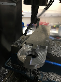
Friday, 23 June 2017

Woohoo - The Startled Man comes alive!!

So far (yesterday) I'd managed to complete the first (roughing) operation using a 20mm HSS rougher and a 3D Adaptive Clearing toolpath. Once I got the feeds and speeds down to a sensible level(!), it went very nicely.

This was the overall machining sequence:

  1. 3D adaptive clearing with 20mm YG-1 rougher (done)
  2. 3D adaptive to clear up with 9.5mm carbide (actually 3/8") end mill
  3. Bore out the counterbores for the cap head fixings with the 3/8" end mill
  4. Drill out the clearance holes for the cap head fixings (4mm drill)
  5. 3D contour to clean up the taper bore with BP300 indexable tool (0.8mm radius) using fine stepdown
  6. 2D chamfer to clean up the top edges (1/2" carbide tool) - where the tool can get in. 
Without much ado, today I ran steps 2-6, one at a time. I relied on the tool table info to get the Z axis distances correct and simply ran the programs once I'd loaded the correct tool in. Bit of an act of faith but surely that's how it's supposed to work. Everything went to plan - quite remarkable! The tool table seems to work nicely, along with the tool length generated automatically using the electronic tool setter and the macro in the controller, so that wasn't a waste of time in the end.

Also printed out the setup sheet which summarises the operations, tools, stickout etc for each step as well as a nice piccy of the setup. Blogger doesn't make it easy to post a PDF, so here it is chopped up into 3 JPGs:
 

It has to be said that I may have been a bit aggressive with the feed per tooth and optimal load for the carbide cutter, as it chattered a bit on the way around. However, that's probably not a surprise given that I pretty much used the manufacturer's max values for the cutter despite my machine being a bit long in the tooth. Next time I'll reduce the feed per tooth from 0.1mm to perhaps 0.05mm and the optimal load from 3mm or so to 1mm. But the finish is not bad and the tool itself was fine.

I reduced the feed rate for the boring operation using the same 3/8" end mill. That went very nicely without any need to pause to clear the swarf, followed by drilling the 4mm pilot holes for the screws. Now The Startled Man has his (startled) eyes!


The 3D Contour cleanup of the taper bore went well, although the 0.8mm radius insert is a bit small to get a decent surface finish. I should try to get some larger radius inserts. The Mitsubishi BAP300 tool body came with some 3mm radius Sandvik inserts but it's clear that they don't actually fit properly. Hmmm.

Finally, the 2D Chamfer was uneventful. Given that this is a carbide tool, I suspect 600rpm is bit on the slow side. I forget what happened but when I worked out the speeds and feeds I probably did them for an HSS tool. I've changed the default settings to 0.05mm per tooth and 5000rpm for next time. That sounds more like it....


After a bit of deburring with a half round needle file, it looks fairly reasonable. The tools are a good fit in the bore and against the dogs. I should probably smooth the bore off with some sandpaper - but only to improve the surface finish and avoid damaging the tools.


And here's the evidence that I retain a full set of intact tools afterwards!
Even Tool 13 (3D touch probe) remains intact. Incredible.

The finishing touches will involve making up the extension piece (amber) and foot (red). They hold the toolholder securely in the fixture while you nip up the collet chuck with the spanner. It should look like this, albeit without the garish colours:
The plan is to hold it in the orientation shown, either in the bench vise or fixed to the edge of the bench or machine table. There will be some form of finger screw (not shown) through the foot to secure the end of the taper while the graunching is being done.

Finish off roughing operation...

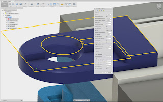
There was a slight clash of the roughing tool with the stock, which I thought was due to the modelled stock not extending as far as in real life, so I added a piece of material and identified it as part of the fixture. Looks as if The Startled Man has developed some form of Eraserhead quiff!

I'd naively thought the toolpath would then avoid clashing - but that would indeed be naive. It even shows up in the simulation (the tool goes red when a clash is found) but messing about with height settings etc doesn't help: 

For now it's hardly an issue as this part of the machining is done and dusted but I'd like to know how to resolve it for next time. Luckily the resulting gouge didn't destroy the tool or ruin the part on this occasion.

Managed to resume the program where I aborted it last night. I figured out that the spiral ramp into the taper bore started at line N8890. To prevent recutting vast quantities of swarf in the hole, I reduced the feedrate temporarily to 50% and blasted it out with an aerosol air duster. Really, I should use compressed air if I can't be arsed to clean out the sump and use proper coolant but that air duster can has been sitting idle (gathering dust perhaps?) for a long time and needs to be put to work.

That was a bit of a slow operation, not least when you forget to turn the feedrate back up after the taper bore. Still, no drama and nothing broken. And as an added bonus, the rubber pants remain unsoiled.

I told it to make manual tool changes (it's made as a tick box setting for each tool in the tool library) and sure enough, after the first operation (3D adaptive), it tried to return to Z0 or thereabouts with that in mind - but then complained about not being able to get there. I must figure out what the issue is at some point but for now I should probably be aiming to post process and then run each operation one at a time. To be honest, that would be good enough, given that I've barely managed half an operation at once so far.

So that's the first 3D Adaptive operation done. 


Next is finish machining the vertical surfaces I just roughed out, using a 3/8" carbide end mill and another 3D Adaptive toolpath. That should be a lot faster due to the higher speeds and lighter cuts. And it's a pretty short operation. I hope I don't ping this tool, as I only have one of them and nothing similar to substitute. It's possibly tempting fate to look ahead more than a couple of steps but if the tool survives this, it will then be asked to machine the counterbores for the cap heads that form The Startled Man's eyes.

It's starting to look like a tool setter now. There is still some material left, to be removed in the finish machining stage, so the toolholders will not fit over the dogs yet. But you can see the general idea.

Thursday, 22 June 2017

Roughing out The Startled Man tool setting fixture. So far so good....

So after lots of neurotic last minute fiddling about with the CAM settings, I thought it was time to either shit or get off the pot / go big or go home etc.

Did some last minute sanity checking and a couple of tight-buttocked run-ups, aborted at the last second. Finally I bit my fist, donned my best rubber underwear and went for it.

These are the tool table settings:

Started out OK but with a full 25mm depth of cut, 8mm optimal load, 0.08mm feed per tooth and 800rpm, it didn't sound too happy when it got stuck in. This may be partly due to the long stickout of the quill and partly due to having the machine vise mounted on top of spacers - both a result of needing to accommodate long drill/chuck and 3D probe. That's one downside of having a turret mill rather than a bed mill.

The difference in material removal rate (MRR) between this HSS cutter and a carbide cutter is quite marked. 800rpm looks and sounds rather tame compared to the indexable tools I was using on aluminium. But still, clearly the machine isn't man enough to play with these tools properly.

So I paused and then stopped the program execution before carefully jogging the tool clear of the work. At least nothing got broken. I think the YG-1 HSS rougher is about £15-20, so I should be grateful.

So I reduced the optimal load from 8mm (40%) to 5mm (25%) and the maximum stepdown from 27mm to 9mm. This means it will have to make more passes and clear the material in several layers. Call me a girl but I suppose I ought to "creep up" on the machine's capabilities rather than seeing if it will drive the tool at 100% of the databook limit.


This time it went well. I don't have any coolant yet (still to clean out the sump), so it was all dry. The roughing cutter generates lots of small swarf due to its "corn cob" serrated teeth. However, once it started spiralling down into the tapered bore, the swarf became long curly ribbons. I may also have overdone the ramp feedrate (233mm/min, almost the same as the normal cutting feedrate of 250mm/min). Anyway, the bore filled up rapidly with curly swarf and I could hear it starting to recut, which isn't A Good Thing, so I made my excuses and left before I broke the tool or made mud. 

It doesn't seem easy to figure out from the Fusion 360 CAM just where I had aborted the program but as it was part way into the first spiral ramp, it shouldn't be difficult to identify where to restart the program - with reduced feedrate perhaps. Perhaps I've missed something in Fusion but never mind - there is a sort of beta version of a backplotter called NC Viewer written by an Autodesk intern that shows you the g code in a panel alongside a graphical display of the toolpath in another panel. 

It seems that the spiral plunge begins at around line N8800, so if I can figure out how to restart the program at a given line number, I can restart the machining just before the point I wimped out. Then I can pause the program and clear the swarf periodically as it clears the tapered hole. That's probably better than regenerating the g-code with girly feed rates.


Sooooo - job sort of part way done. Doesn't look too bad: 

  • No broken tools.
  • No (severe) gouges.
  • The rougher insisted on roughing out the chamfered edges(!!). I didn't pick up on that but apart from wasted time, no harm done. It did a bit of a lead-in and lead-out (visible to the right of the first pic, if you look closely), not realising that the stock actually extends out past the work - but we got away with it this time....
  • Some of the moves were slow, presumably due to the "stay down" setting for small moves.


Wednesday, 21 June 2017

Freesteel - the original adaptive clearing algorithm - and Motorola rant

It's lost in all the hype but worth recognising that the breakthrough in CNC machining that is called "adaptive clearing" was made by a couple of guys from Liverpool back in the early noughties. It's all been subsumed into firstly HSMworks and finally Autodesk (after they acquired HSMworks). 

Julian maintains a blog ("Freesteel") that incorporates some of the early material and it includes an interesting brochure from those days.

It's clear that his experience of being part of Autodesk was not a happy one. It has distinctly similar echos to my time at Motorola, where corporate bullshit, management bollocks and sheer incompetence was an evident prerequisite for advancement into senior management. At Motorola, we could look forward to a bullshit-packed CEO's email each month from Chris Galvin and his henchmen. I could almost say I miss these now, as they were so rich in vitamins.

One key benefit resulting from the acquisition of an exciting new player or competitor is the ability to stifle competition or unwelcome near innovation. This was demonstrated close to home when Motorola acquired TTPcom in Cambridge for £100M - then promptly sacked all the staff and closed down the business. An endless cycle of growth, retraction, redundancies, company sales etc to maintain the share price (and their bonuses presumably), finally left the company up its own arse. Motorola today is a tiny vestige of its former self (150k employees when I worked there in a wide range of sectors, 40k today, clearly struggling and solely in telecoms). It is a mere shadow of its former self.

Of course, Galvin considers himself above any form of responsibility for the demise of Motorola. In fact, in a Wikipedia entry clearly written either by himself or some worthless sycophant, he considers himself to have turned the company around and delivered a transformation. Mercans seem to be big into believing their own bullshit. The harder they struggle and the more they fuck up, the bigger the beast they are. Making a complete mess of something, then battling to contain the resulting shitstorm seemed to be a surefire recipe for recognition, whereas quietly making a success by careful competent execution was a thankless hiding to nowhere. Presumably there was some "constructive upside" to the acquisition and loss of TTPcom for £100M that only someone of Galvin's intellect could possibly comprehend, even if he did seem curiously unable to articulate it.

Of course, Motorola was started in 1928 by Galvin's grandfather, so it may be no great coincidence that his rise through the ranks was almost meteoric. And that possibly didn't help him to avoid delusions of grandeur. There's that "entitlement" or "ownership" problem again.

There is a Lancastrian expression "clogs to clogs is three generations". The first generation founds a business, the second generation grows it and the third generation plows it into the ground, being incapable of even pissing into a paper bag. There are many examples of this out there.

Thankfully, some parts of Motorola live on in other forms, eg the AIEG (automotive) division I was part of has been part of Continental for many years. That could only have been a significant improvement for all concerned.

Sunday, 18 June 2017

Tooling up again

Now that I've identified the tooling required to make The Startled Man, I need to stop dicking about and set up my tool table. I need 5 different tools to do the business and I want to be able to change the tools over in the middle of the program without having to fool about changing G54 etc.

So the procedure highlighted previously was used:

  • Set G53 (ie use machine coords), then for each of the tools in turn:
  • Select the correct tool and length using G43 T**H** etc
  • Run M882, then "redeem" the position into the table for that tool
You can enter the commands in the MDI and then run them by commenting out the ones you don't want.
Seemed to work OK.

I managed to use the Mahrtest probe (just). It's too long really but it worked on this occasion. Obviously this is tool number 13 - it didn't require much thought!!

So now I have the whole line up of tools (5 off) set up, plus the Mahrtest probe. I also have Tool 1 defined as the short 6mm pointy rod which is useful for doing air cutting.
Did a bit of air cutting. The graphics display is a bit lame. It only generates a tool path trail when the graphics mode is enabled. If you switch back to the main display mode, the graphics trail stops so when you go back to graphics mode there is a big gap. 
The machine is now set up. The tool lengths seem to be correct, the air cutting looks good. What could possibly go wrong?
Time to go big or go home!

Saturday, 17 June 2017

Electric tool setter

I've been a bit sloppy with my terminology. Although I've been calling it a tool setter, the "startled man" fixture is actually a jig for tightening collets etc without damaging the taper tooling or myself. It's not a tool setter as such. Professional fixtures are f expensive, which is why I'm planning to make one as a test of my CNC skills. Even acquiring the right sized stock has been a challenge but now most of the pieces have fallen into place.

A electrical tool setter is simply an electrical switch that indicates when the tool tip has touched off on a surface. You really need one of these to determine the length of each tool with some accuracy, for instance if you want to populate the tool table with tool lengths. The Newker controller has a macro (M882) to do this for you but it requires an input (X25) to be grounded when the tool touches off.

In theory you could just place a metal block on an insulator, connect it to the X25 input and rely on the (grounded) tool to tell the controller when contact has been made. But that wouldn't be very clever because the machine can't stop instantly and the result would be a broken tool. So you need a spring below the touch surface and an accurate register for the touch surface to locate against in the vertical direction.

Nothing complex about it. I actually have a pukka Renishaw touch probe that could be used on the face of it but at this stage of my CNC experience, mistakes come easy and frequently. Replacement tips are not cheap! Besides, instead of a spherical touch probe tip, you really need a flat surface to touch the tool length off against, as many tools don't actually have a surface at the centre of their end face, eg a classical end mill or a face mill.

You can get cheapish probes on Aliexpress and ebay but it's clear that they aren't up to much. For now I just need something simple but reasonably repeatable.

Here's what I drew up, having identified a suitable piece of Tufnol in the scrap bin:

Simple enough concept:

  • Cylindrical Tufnol body, which is conveniently electrically non conductive.
  • Simple, flat-topped steel piston
  • Helical spring to hold the piston against the internal register at the top of the body
  • 4mm banana socket insert to provide the electrical connection to the piston (via the spring) and also to retain the spring and piston in the body.
Then out into the workshop to flash it up:

Tufnol drilled out, then bored to size.


A piece of mystery metal. Clearly steel but not exactly free cutting. Turn down the nose, chamfer, sand smooth and part off.

Face off, drill and chamfer.


Drill 5mm cross hole for banana plug insert. 4mm blind hole at the far end for the nose.

Make up a spring from a length of 1.6mm stainless steel TIG wire. It's not exactly critical so it's simply a matter of hit and hope. It seems to have come out OK.


Finished item

And said item in position on the machine. Without getting carried away, it seems pretty repeatable on the basis of a few initial tests. Certainly, I expect it will be good enough for the likes of me, for now at least.

Bottom line is - I followed the procedure I described previously for auto populating the tool table using the M882 macro and a couple of dummy tools (one shown in the photo). With the tool setter, it becomes pretty quick and easy. 

So now I can set up the tool table for the various tools needed to make the "startled man" tool fixture!
The CAM is starting to look reasonably sensible now:
  1. 3D adaptive clearing with 20mm YG-1 rougher
  2. 3D adaptive to clear up with 9.5mm carbide (actually 3/8")
  3. Bore out the counterbores for the cap head fixings
  4. Drill out the clearance holes for the cap head fixings
  5. 3D contour to clean up the taper bore with BP300 indexable tool (0.8mm radius) using fine stepdown
  6. 2D chamfer to clean up the top edges - where the tool can get in. 

Looking at the recent video from NYC CNC, it seems that the 3D adaptive with the 9.5mm tool may be able to do the counterbore if you "detect flat surfaces" and change the value of the plunge radius(?). If so, I may be able to get rid of the boring operation, step 3.

Wednesday, 14 June 2017

Taking stock

I seem to be living in a steel desert. Although there are several steel stockists around Blackpool and Preston, they seem to only sell in 6m (or 7.5m) lengths. So when I am looking to buy a piece of 25x100mm flat stock or a length of 130mm round, there is a problem.

I thought I'd cracked it when I looked at the B&M Steel website. They almost sound public friendly...

...but you'd be wrong. The guy said they would cut my 6m length for free and you don't have to take more than you need. But you'd still have to pay for the full length. What a joker. 

The next best hope is to find a fabricator or machine shop that would sell cutoffs or short lengths. I found a couple of these locally but generally fabricators don't deal with the sizes I'm after. I rang a few steel fabricators and stockists but so far I have yet to find somewhere suitable. The search will have to continue.


So I swallowed my pride and bought some steel from Jenkins Steel Online. Basically you pay £18 per item for carriage, plus the cost of the steel itself (about £1.10 - 1.20 per kg). The order was processed yesterday and arrived today by Parcelfarce 24. 


This is what £98 of steel looks like:

One issue I hadn't anticipated was the challenge of how to cut 130mm dia bar in a 110mm capacity bandsaw. It bottoms out before the bar is parted.
The whole cut took 36 minutes. 
As well as the round bar, I got 500m of 25x100mm for the tool setting fixture. This should allow me to make some chips again:
The startled man, he say yeh!!

Arc Captain MIG200!

Yes indeed. Not content with a solitary TIG200PACDC TIG welder , I've gone for the matching pair. ie the MIG200 sister unit. There was ...