There comes a time when you just have to press the button and let it do its thing:
Outer profile - 2D Adaptive and 2D Contour:
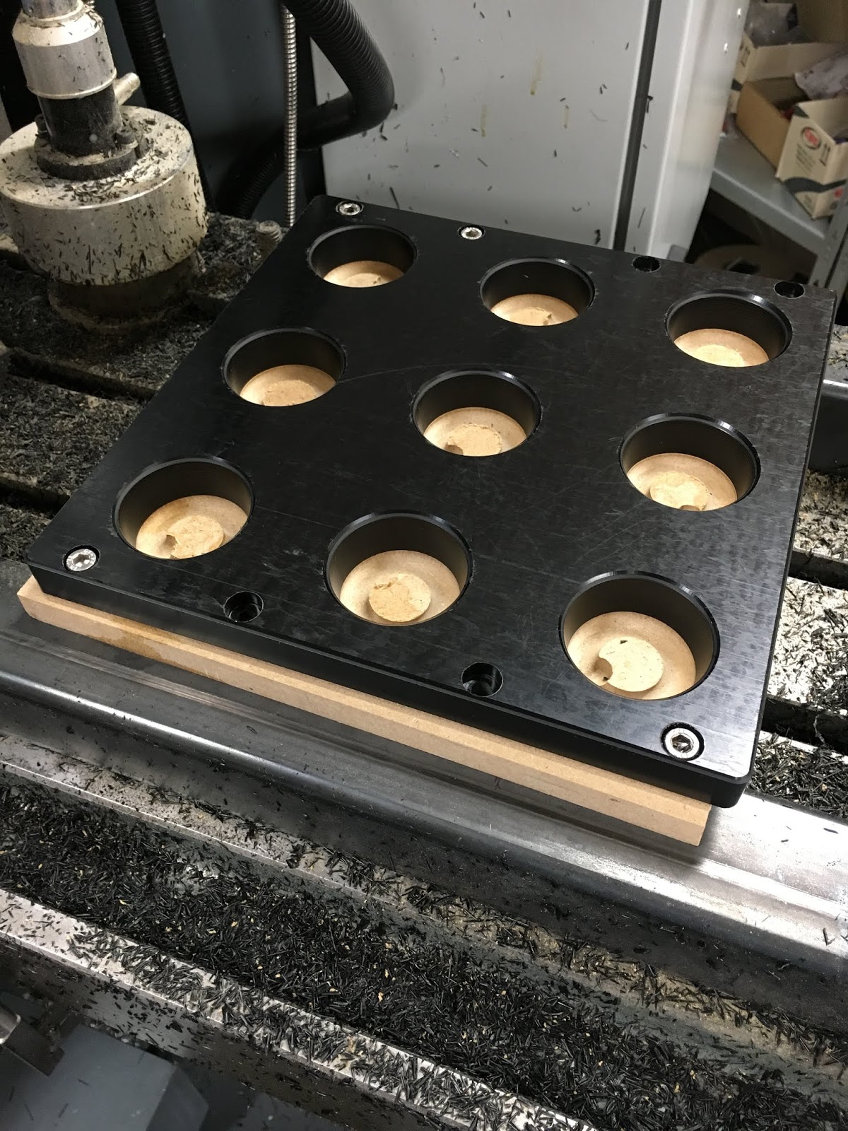
Roughing out the bores:

Using a ball end mill to create the tapers:

Not bad:

Chamfering bores and outer profile:
Job done, bar a bit of deburring:

Happy with that:
My main impression - that was damned slow. I was expecting to be shifting a lot more swarf a lot quicker. I think I can safely up the chip load (mm/tooth) from its 0.05mm to something a bit more serious. Admittedly a single flute cutter is going to make fewer cuts per rev than a multi flute cutter but what's the point in having a large flute if you don't make full use of it to shift proper swarf? Next time.....
Machining the legs:
The final part(s) were the 2 "legs" to hold the tray off the deck. Not worth buggering about with Fusion 360 when it's a question of squaring off some simple rectangular stock to size and drilling 4 holes in each. With the wireless MPG pendant and the DRO display (which is duplicated on the MPG itself), it's a simple matter of squaring off, measuring it up and then incrementally adjusting the overall dimensions to get to the final size.
I just used my 18V cordless circular saw to chop a couple of pieces off the big piece. The finish wasn't too bad but it's far from flat:

With APGT1604 polished inserts in the Korloy face mill, the finish is pretty decent:

Manual operation using the DRO is pretty effective. I'll settle for that:

As for the holes, I could simply have drilled them manually, positioning the holes using the DRO but this seems an ideal opportunity to get into the "canned cycles". A quick 2D drawing gives the critical dimensions:

Using the "array of deep drilled holes" function, I flashed up the required g code. As I have cleverly arranged for the holes to be unevenly placed for some reason (no idea how that happened), it's actually 2 sets of 2 holes per leg.
By placing the 2 pieces back to back in a mirrored arrangement, the rows of holes are 15mm apart and all 8 holes can be made in one go:

You firstly add the tool number, drill size, speed, feedrate etc, then the actual operations using that drill are specified on the following lines.
Here's the whole operation in its entirety:

The "deep drill" operation retracts the drill fully after each peck to clear the swarf.


With the correct tool loaded, you need to set the X, Y and Z positions in G54 (using the "zero axis" function), then off you go....
Used a collet chuck to minimise stickout.

Manually tapped the M6 holes (well, using a cordless drill) and used the belt sander to fillet the remaining edges on the legs so that almost blend with the main tray body/
The bottom line:
Here's what we've got finally:


Happy with that!


No comments:
Post a Comment