Mounting the switches on the machine was only half of the job. Actually wiring them all the way back to the controller is a bit more work. I need to collect the various switch connections together in some sort of junction box and then bring those signals back to the cabinet. Finally, the in-cabinet wiring needs to take the signals to the appropriate pins on the appropriate connector on the back of the controller.
I've gone to sensible(?) lengths to make the machine wiring reasonably fit for the purpose by removing the crappy (original) D connectors and nasty line driver from the DMM Tech servos, replacing them with a 3D printed housing on the motor, proper oil-proof drag cables and a more workmanlike line driver for the encoder. So I plan to make a half decent job of the limit switch wiring as well.
I'm not a professional machine builder and this is not a professional machine installation but I'd like it to stand up to the coolant and swarf that I can reasonably expect it to encounter without malfunctioning.
Junction box:
Found a sensible looking IP66-ish box on the shelf. Looks like ABS or similar. And I have several bags of various cable glands.
I'll stick a large gland on the side of the box (for the main drag cable back to the cabinet). This is my temporary grinding booth, used for grinding / welding my steel gate posts:
I'm using some of the 9.5mm pitch barrier terminal for interconnections. The empty ways have been removed to make room for the fixings (stainless self tappers). And I'm using 4 smaller glands for the individual limit switch cable entries:
There you are. Just need to do a spot of wiring up now....
Inside each of the IMO limit switch assemblies is a switch module which simply lifts out. It has one set of NC and one set of NO contacts:
Here's one wired up (the Y L+ switch). I'm using the NC contacts, which are generally the recommended flavour for limit switches, e-stops etc:
Here's the first one terminated at the junction box. The large cable glands DO actually tighten down onto that small cable!
This wasn't quite right. In fact you can angle the crimps so the tuck into the slot between the screws. The specified crimp dimensions shown in the datasheet aren't the usual size of course.
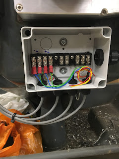
Here they are, all switches connected up:
It's a 4-core screened cable. Yeh, yeh, it's not proper drag cable but I don't have anything suitable on that front. At least it originally came from a proper machine (from the original Shiz cabinet). I've left the 2 spare wires in place in case I need to use them for the homing switch inputs. Didn't connect up the screens, given that these are 12V level signals (= high noise immunity) and all the other noisy connections elsewhere in the system have been screened at source:
The main (green!) drag cable in place and connected up:
The black bundles are unused screened pairs. May as well leave them, just in case they are ever needed.
Seems to be connected up correctly. They show up as NC until you actuate one of the switches. The X and Y axis +ve limit switches are in series, ditto the X and Y axis -ve limit switches.
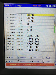
That's working now. If you are jogging or homing and actuate the switch, a red message comes up and the machine stops until you press the reset button.
No homing switch as such (yet), although I think it's a fairly simple matter to use one of the + or - limit switches as a homing switch. Wouldn't be very repeatable or accurate but would allow me to home the machine until I figure out how to implement the proper home switches.
Resetting machine coordinates:
One problem currently is the machine coordinate setting. I expect it's simple enough to zero the coords but I can't see / recall how to. Once I have something connected up to the home switch inputs, I can probably rectify that. However, currently it shows the machine origin around 11m and 23m away from the current position(!!). As the soft limits are something like 0 - 350mm (X) and 0 - 250mm (Y) for now, it thinks the table is beyond its soft limits and will only allow motion in the -ve direction.


