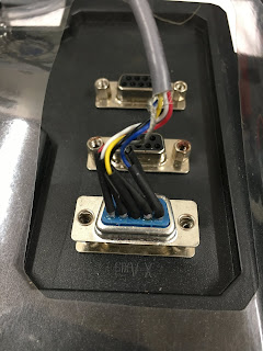
The Newker 990 controller has encoder inputs for all axes, so if you happen to have scales on your machine (as I do on the Blidgeport), you can use them to provide positional feedback and potentially reduce the effects of backlash etc. Most backlash is distinctly nonlinear so "normal" PID controllers are incapable of seamlessly using encoder info in closed loop.
Not convinced it would transform the performance but if my machine setup isn't too bad, it may be interesting to try it out. All that is required on the Newker controller is to connect up the encoders to the back of the unit and configure the Other Parameters to the correct scale factors. Obviously it would be helpful to have the same scale factors on both the servos and the encoders, so that may require some buggerage to get right.
The Newker has double ended / differential inputs (A+, A-, B+, B- etc) but glass encoders seem to come in both single ended and differential versions. Which have I got? And beyond that, whichever flavour I have, what are the connections?
The display unit:
Best way is to open up the DRO unit, the connectors and the encoders themselves. Here's the DRO display unit. I've always speculated on the horrors within, in terms of the safety or lack thereof. What better way to find out than whip the back off and take a look.
Off with the back:
Shitty little PSU here. This is where the mains hazard would arise. It's a bit messy but I've seen worse.
There's a QFP144 package (possibly an FPGA?) to do the pulse counting etc, a micro(?) that presumably does the clever functions and 3 display drivers for the coordinate displays - this is a 3 axis version. It's funny to see the part numbers have been ground off the micro, to stop people reverse engineering it, given that China is the Wild East of bootlegging.
The encoder head:
As for the encoder head itself, the output seems to have a quad comparator (LM339) and 3 pots to do the final signal generation.
And at the other end, there are only 5 wires (plus shield). That pretty much tells you there are only single ended A, B and Z signals plus the 0V and +5V signals. So all I need to know now is what are the connections. I can connect up the inputs single endedly almost certainly. One way to find out.
Crappy D connector shell.
It still seems to work. I should be pleased.
The connections:
The connections are shown in the Newker manual:
These are the D connector pinouts. Not certain which output goes to A, B, Z etc but the pieces of the puzzle are mostly there now:
At some point, I'll need to power it up and look for the appropriate configs. This could take some time. In the meantime, I should dig out the manual and do some more reading up. It's been almost 2 years since I last looked.....


No comments:
Post a Comment