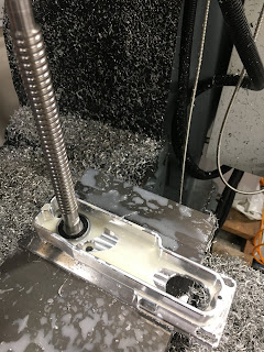
I did the CAM for this last weekend and having sanity checked it again, it looks pretty good to me. So, set up the toollength offsets for the 2 drills, generate the g code and hit the tit. Let's see what happens - no point prevaricating, just send the fucker.
First, pick up the workpiece origin, as described last time. The Z axis is zeroed on the top of this ground parallel:
The Y axis is set on the face of the front jaws:
and the X axis is picked up on the end face of the work, with a 5mm slip gauge to allow the probe to clear the stock overhang. Then the X measurement is offset by 5.0 + 1.07 = 6.07mm. I now have my machine workpiece origin set at the same place as the CAM has it.
And.....we're off.
Here's the video version:
And the still version:
Looking good....
Done. No cockups and no broken tools.
Messed with the tool diameter offset to open it out a tad. I suspect this is actually due to noncircularity caused by backlash, rather than incorrect tool diameter but the result is the same - the bore ends up needing to be taken out a little. Here it is after a couple of spring passes and some finessing of the tool offset:
Doesn't look too bad. The main offpiss is the excessive chamfering on the topside and the wrong (too large) bore for the servo motor register, as noted last time.
Can't pretend I'm entirely disappointed with the end result. I'll need to think about the cover next.


No comments:
Post a Comment