Whoa, Fat Boy. Before starting yet another escapade in the workshop (the ATC for The Shiz seems to be the latest wheeze), you need to finish what you started, namely the CAD and CAM design of the "final"(?) revision of the Z axis for the Bridgeport CNC conversion. Otherwise the workshop will see yet more jobs that never get finished. The ATC needs to wait!
The current status:
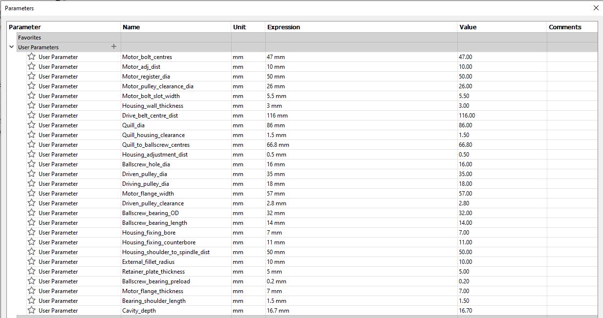
Last time I recreated the Z axis motor bracket / housing using parametric dimensions with the intent to give some flexibility on motor sizes. It was in danger of becoming a bit overwhelming but the end result works reasonably well. I can change the bearing dimensions or the motor flange size and most of the dependent dimensions are automatically updated to suit.
I tried to design the housing from the functional requirement, rather than iterating what I ended up with last time.
But that was just the housing. To complete the job, I need to update all the other components in the head assembly, such as the bearing model (4201 size now), the modified ballscrew, the new pulleys (now 10t and 18t) - and of course the head casting model itself, which needs to be corrected (spindle to ballscrew centre distance and various minor features). I also need to add the "simple" ballnut yoke.
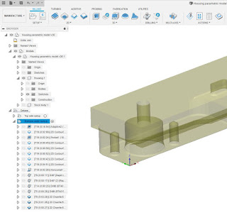
CAD completed:


CAM created:


Most of the work is done with the long series 10mm carbide end mill, which is a fine beast. I try to use as much axial length as possible, which is how they are supposed to be used. This makes the most of the HSM toolpaths and cuts out a lot of crap, as well as leaving a superior finish with little or no visible stepdowns. As long as you don't get carried away with the optimal load (radial depth of cut), there isn't any chatter. And taking a finishing spring cut ensures there is little if any unauthorised material left at the end.
I blasted a 10mm drill through the stock at both locations where the end mill is expected to spiral down into the stock to create the cavities for the motor and ballscrew bearing. This not only helps the end mill to spiral down into the stock but also allows the coolant and swarf to drain away. Recutting swarf seems to be the biggest risk to the life of cutters, especially when achieving half decent MMRs.
Stock cut up:


Here they are, all set up and ready for action:

Metal cut:
This went pretty well although I caught it trying to do as it was told, which was to try to mill the 6mm slots using a 7mm drill. That wouldn't have ended well for either the drill or the workpiece. The giveaway was when the spindle sped up to 6000rpm with the drill still in place, when I had planned it to change to a 4mm carbide end mill. As the ramp feed rate was fairly modest, being a small end mill, I had enough time to shove The Stupid Fat Bloke out of the way, figure out what was going on and stop the program. That bloke needs a smart cuff over the back of the head, or possibly a horse whipping.
WTF happened?
Turns out I'd called both the 7mm drill and the 4mm end mill Tool 5 in Fusion 360, when the end mill had been set up in the machine as Tool 14. Obviously the machine didn't see any need to stop the spindle and ask me to change from Tool 5 to Tool 5, so it just carried on. Machines do as they are told!
I created a separate program for the last 2 operations, namely the slots and the final chamfering.
Final result - top operations?


Came out well:


The chamfering was a bit heavy. Turned out The Stupid Fat Bloke had set the chamfer size to 1mm - I told him to set it at 0.5mm. Also he set the motor register diameter at 50mm, not the approved 38mm. I've fixed that in the model and given him another fat lip.
Bottom side CAM - Setting up:
Next will be the bottom side operations. The tricky question is usually how to pick up the "same" part origin once you have flipped the part over. This point is the best I can think of, as I don't have any precise feature that passes through the whole body. The through holes were drilled using a std (stubby) twist drill, so not very precise.

I can pick up the Y and Z coords from the top face and the X from the highlighted face below. However, the part origin isn't on the face - it's offset from the origin. I will probe that face and then tell the machine its actual position, which is not zero on the X axis (it's X-1.07mm).

Having machined everything I can manage from the "top side", I like to export the remaining stock (after the top ops) as a body, then use it as the stock for the remaining operations. Here's how to create a body from the last completed operation. It works well but you need to know how to do it!
Toolpaths:
Here's the setup for the next ops, with the stock model carried through from the top side operations:

Almost all the work will be done by the 10mm long end mill. Then a couple of drills for the fixings (M4 and M5), then finally some chamfering.

Should result in this:

Machine setup:
The precision(?) ground parallels should help here. I can pick up the X from the machined face on the left (offset by 1.07mm), the Y from the rear face of the parallel that's poking out from the vise in the next photo and the Z can be set from the top face of the same parallel.
In fact, I've changed the stock origin to the point shown here, as it's going to be easier to pick up than the one I chose previously:
Here we are in the vise:

It's set up now, ready for action. Sounds simple - what could possibly go wrong?
Right, that's it until next weekend. Hopefully I will be able to machine this up on Friday evening. Looking reasonable so far....


No comments:
Post a Comment