Wossup now, Fatty?
There's no point me getting too carried away getting the Bantam all boxed up and tidied up before I've made a decent job of adjusting all the various gib strips etc. Currently, it's functional but when I last assembled it all, I simply bolted it all together to check out the function, rather than set it up finally for accuracy. That time seems to have arrived now.
The cross slide is fairly straightforward and can be adjusted without any disassembly being required - you can loosen off the locking screws and adjust the gibs from the top and side of the cross slide. The top / compound slide is even simpler, as I'm not using it any more.
But the bed ways on this machine are the classical "flat and vee" design. The vee ways provide radial(?) location of the saddle (ie in the X axis direction, the direction the cross slide moves in) as well as vertical location (the weight of the saddle and cross slide assembly plus the machine loads), while the flats at the rear simply provide vertical location.
I haven't modelled the front saddle gib (and its friend, the saddle lock) yet but I've sketched it in to this screenshot (red).The saddle ballscrew that drives the saddle up and down the bed is a funny pink colour - it's also quite a way from the front vee.....
What's the problem with that?
One drawback of my choice of location of the ballscrew at the rear of the saddle is the twisting moment that results from the distance of the ballnut from the vees. On the conventional machine, both the leadscrew and the feed rack are almost directly underneath the vees, resulting in minimal moment. Obviously, if I have any loose play in the vee, the whole saddle will want to go out of square when any kind of load is applied through the ballscrew / ballnut.
In order to minimise the movement that would (will!) arise from this effect, I'd need to have the front gibs nipped up pretty tight. The vees are something like 90 degrees included angle, so will want to bind when a twist is applied. This all feels rather suboptimal.
In fact, I'd say this was a bit of a serious fuckup. I really can't see any sensible way of making this work acceptably. Time to stop and have a (re)think?
How did it end up like this?
It's the usual story. I wanted to retain as much of the original features and functions of the Bantam as possible. This meant fitting the X axis (longitudinal) ballscrew at the rear of the machine, even though I could see that wouldn't be quite ideal.
However, having got the system up and running, I've now removed the apron with its cross slide and saddle handwheels, as they add nothing except inertial mass and generally get in the way. This leaves the whole of the front of the machine clear after all. I really don't see myself refitting the manual controls at any point, so perhaps this is the time to have a bit of a rethink about the X axis ballscrew location. Really? Dear god, are you taking the piss?
Let's strip things down:
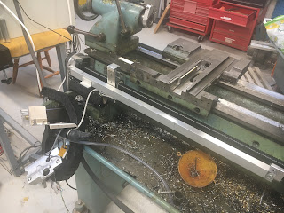
See what I mean - things are nice and simple with no apron:
Here are the front gib strips (looking up from below). The RH one is also the saddle lock, hence the slit.
The operation manual says that the only way to adjust the front gibs is by machining them. WTF?? Certainly, loosening the carriage lock results in noticeable vertical movement when I try to lift the front of the saddle. That's not ideal but there's no simple workaround. Bollocks - some sort of adjuster may need to be crafted up here.
Round at the back:
These counterbored fasteners (3 off) are the lock screws that hold the rear gib strip once the vertical clearance has been adjusted.
Let's remove the rear swarf guard thing and strip the gubbins off so we can get a closer look.
That's easier to see. First, off with the rear ballscrew guard, exposing the servo drive, rear limit switch and encoder head.
The cross slide simply slides off once the 2 ballnut fasteners are removed. That Oldham coupling will be coming off, now that I've jettisoned the cross slide handwheel after all.
The motor comes off next
I should really remove the limit switches before they get ripped off by The Stupid Fat Bloke.
Rear limit switch:
Front limit switch
There. Just the saddle remains now:
The rear gib strip assembly can now be seen properly, under the saddle:
Here's the rear gib assembly after removal. It's actually lying on its side. You can see the 3 height adjusters, as well as the 3 fasteners that secure it to the underside of the saddle.
You can see how the height is adjusted. There's no mention of this in the manual and even the exploded parts list doesn't really help
Oops. We seem to be undergoing a surprise audit.
It's always good to get the approval of the workshop supervisor. I think that was a nod, so all seems to be in order.
Enough?
Bollocks - let's also whip off the X axis ballscrew and ballnut. In for a penny, in for a pound! Obvs at this stage I'm going to be fucked if it turns out I need to turn anything. Perhaps I can refit the apron if I desperately need to do any manual ops on the lathe, otherwise I will have to rely on The Shiz for everything.
Let's do some CAD work to figure out a better solution.....


No comments:
Post a Comment