Get it together, Fatty!
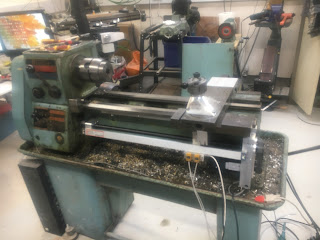
Finally got the whole saddle (Z axis) drive completed and assembled. For the "free" end of the ballscrew, I bent up a piece of steel strip that bolts to the bed casting and picks up the bearing housing and the end of the encoder scale. It's not quite as solid as a loominum or steel lump but the rough casting shape would be pretty difficult to create a mating part for.
Finally got the whole saddle (Z axis) drive completed and assembled. For the "free" end of the ballscrew, I bent up a piece of steel strip that bolts to the bed casting and picks up the bearing housing and the end of the encoder scale. It's not quite as solid as a loominum or steel lump but the rough casting shape would be pretty difficult to create a mating part for.

All done now. And I have managed to increase the saddle travel over what I'd been seeing with the ballscrew on the rear of the machine. I'm now getting 19" / 480mm total travel, which compares well with the specified 20" between centres - it doesn't specify the saddle movement as such. I'll retain the adjustable saddle stop near the headstock to prevent crashing into the chuck / faceplate etc.
A bit of buggerage reconnecting everything up and swapping over the Z axis limit switches (which have become flipped in the transition), then we have life again.
Anyway, now that I've got it all back together, is it any improvement on what I had before when the ballscrew was rear mounted? Bloody better be!
Backlash testing:
Initial results were pretty crap to say the least. I was seeing something around 60-80um of lost motion - WTF?? All this buggering about and the backlash was worse? Clearly something was amiss.
Sure enough, The Stupid Fat Bloke had been busy again, assembling the saddle drive components loose, then forgetting to actually tighten them all up finally. One of the fasteners holding the ballnut yoke to the new saddle bracket was rattling in the wind and its friend was only loosely nipped up.
It takes some time buggering about with the various fasteners and positioning the various joints to ensure there's no binding or divergence between critical parts as the saddle moves along the extent of the bed ways (The Stupid Fat Bloke likes to call this "machine fitting"). If you really messed up when doing this, you could wrench the read head from the linear encoder and/or stress the ballnut - best avoided.
So here's the Z axis (axial ie along the bed):
That's pretty encouraging. Although the Baty DTI has only 10um resolution, the backlash is hard to discern ie not much more than 10um. Given that the encoder has a 5um resolution, I've got no business expecting anything better. Of course, in practice, with everything moving about and cutting forces in action, it won't be as good as that anyway.
As for the X axis (radial ie cross slide), it's pretty similar:
Conclusion?
Well I think I can be happy with that - TFFT. As for further improvements to the accuracy, we are at the threshold of ladling lipstick onto a pig. It's a vast improvement on what I had as a manual machine. One of the main practical limitations is the resolution of the encoders. The miniature magnetic encoder I've buried in the cross slide has a resolution of 5um and that can't be improved from what I can see from available products. I could improve on the Z axis resolution but that might be rather pointless if the X axis is 5um and I expect pig lipstick is rather expensive anyway.
Well I think I can be happy with that - TFFT. As for further improvements to the accuracy, we are at the threshold of ladling lipstick onto a pig. It's a vast improvement on what I had as a manual machine. One of the main practical limitations is the resolution of the encoders. The miniature magnetic encoder I've buried in the cross slide has a resolution of 5um and that can't be improved from what I can see from available products. I could improve on the Z axis resolution but that might be rather pointless if the X axis is 5um and I expect pig lipstick is rather expensive anyway.
What next?
- I need to fit the telescopic covers to the exposed Z axis ballscrew, to keep the swarf out of the ballnut. Of course, when I do that, it's quite likely I'll then have to disassemble it all again. That's how these things work.
- Also, make up a cover for the cross slide, to keep swarf and coolant off the ballscrew. The cross slide body is like a Swiss cheese due to the myriad original holes (for various tool posts and steadies) and the (12?) extra holes I made for the solid tool post. I'll probably use some loominum sheet for that.
- Then at some point I will actually mount the control cabinet on the machine itself and wire it up for good. Currently I've got the cabinet on the bench and brought them in loosely through the open panel at the base. Once mouted on the machine, access to the innards will become "inconvenient", so I need to be convinced that the bulk of the buggerage is over.
- Before doing so, I need to give thought to providing some additional limit switches.
- One would provide some degree of adjustment for the limit switch near the headstock. This could simply be an adjustable target for the proximity switch.
- Another would account for the tailstock movement. This would probably need to be a proximity switch on the front of the tailstock or the side of the saddle.
- Possibly also some means of preventing the toolpost crashing into the chuck or tailstock. Currently, I could easily traverse the saddle up or down the bed with the toolpost near the centre line. This could cause a fine crash.
- I'm thinking of a pluggable, secondary limit switch perhaps. Some more consideration is required but a safe option may be to fit a connector on the housing and wire it into the 7i76, then I can connect it up as and when I have something figured out.
<END>


No comments:
Post a Comment