As noticed previously, the saddle has 2 sets of gibs - one at the rear and one (pair) at the front. The rear gib has a means of adjustment to take up any vertical wear but bizarrely the front gibs don't offer any means of doing so. Clearly the front gibs are not considered to be anything more than a means of preventing the saddle being lifted, while the rear gibs are considered critical to the correct function.
Presumably the rear gibs are needed when the rear toolpost is used with the tool inverted, to control the height of the tool relative to the spindle. In the front position, the tool loads will hold the saddle against the vee way.
Although the saddle vertical slop may not have been considered critical by Colchester when the machine was designed, I plan to reduce it back to something closer to how I suspect it was shipped. Besides, I've already seen how an off-centre load on the saddle can result in the saddle being lifted as a result of the moment acting on the vee ways. Although moving the ballscrew to the front of the machine (where the original leadscrew was) should have eliminated that problem, I want to get this machine set up accurately while it is in bits.
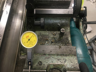
Let's do some measurements to see how much slop there is with the current setup:
Short gib strip slop at headstock end:


One step at a time. I'll see how this butchery of the short gib works out, then figure out what to do with the long gib....
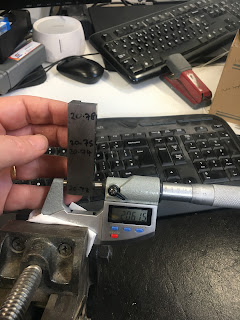
Managed to remove around 120um from the short gib, bringing the thickness down to a fairly consistent 20.6mm or so.
Then refitted it and measured the resulting slop. How does that shape up? At the tailstock end I'm seeing almost no measurable slop - perhaps 5um at most, yet no binding. Sounds as if I managed to hit the spot there. And at the headstock end, I can measure a smidgen over 20um - perhaps we can call that 25um. Happy with that.


TBH, I could probably get away with leaving the long gib as it is but as I'm here, it would seem rude not to finish the job properly.
Here's the long gib before being butchered. Given the slop seen above, I'd imagine taking perhaps 150um off the thickness:

The long gib slop measures 170-250um, depending where on the travel you measure it. I'll have a go at removing 160um and see where that gets me. So a final thickness of just over 21mm sounds possible.As long as I don't fuck up and take too much off (and cause the saddle to bind), it can only help....
Rear gib adjustment:
Hmm. Before I can get into the gib adjustment, I need to remove all the gubbins from the rear of the machine. All that stuff has to come off anyway, so there's no time like the present.


Nothing much to see beyond this. Took a fair bit of buggerage to adjust the 3 screws to minimise any vertical slop while avoiding the saddle binding anywhere on the bed.
Right. That's the various gibs set up. Now let's start to reassemble the drives...


No comments:
Post a Comment