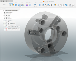
I started out on this project some time ago. The aim is to allow me to reuse all the D1-3 spindle tooling I have accumulated over the years for the Colchester Bantam on my Tree CNC lathe which has a different (A2-5) taper nose. This will mean I won't need to spend squillions on acquiring all manner of chucks etc for the Tree. This is my design for a "D1-3 to A2-5" adaptor. I've made most of the components now and am keen to get this wrapped up and in use before the sun freezes over.
Previously, I made and hardened the cam pieces for the D1-3 adaptor Having made the body and cam pieces, I must surely be approaching the point of completion for this particular project.
Where are we? This looks like the sequence of outstanding actions:
- Drill and tap the holes for the cam retainers.
- Machine up the cam retainer screws. These are M8 grub screws, machined down to a ~2mm nose - they mate with slots in the cam pieces. I will use a mild threadlock adhesive to hold them in position.
- Mount the adaptor on the Tree's spindle nose and machine the D1-3 taper to final size in position. IIRC, I left it marginally oversize.
- Clean it up, finally fit the cam retainers and consider it job done.
The scheme looks like this. I've opted to fit the modified grubscrews from the front face, so that I can remove the cam pieces without needing to dismantle the adaptor from the machine spindle, rather than follow the original plan to screw them in from the rear. This change of plan makes them rather short and stubby but I think it's a sensible change.
To fit the retainer grub screws in their correct positions, I will need to locate the centre coordinates. For this, a 2D drawing is the simplest approach. I can read off the coordinates and simply type them into the Centroid CNC12 MDI.
But it would be almost impossible to set up the stock at exactly the correct orientation without a significant amount of trial and error.
Luckily, the Centroid s/w includes a "CSR" (Coordinate System Rotation) function which probes a plane surface and rotates the machine's coordinate system so that it is aligned with that plane rather than the machine's axes. This allows you to set up the workpiece without needing to worry about aligning it perfectly with the table. For this, you need to use existing features on the workpiece - in this case, I can pick up from 2 of the mounting holes using a couple of drills and a precision parallel. The drills are a nice fit in their holes. Like this:
Holes drilled and tapped M8:


No comments:
Post a Comment