Nothing much to the stick welder, beyond finding some sticks and a few bits of scrap steel and off it went. Surprisingly easy to use despite the passage of time (must be about 3 years).
The MIG welder (Italian CEA "Monomig 180 CAR") always seems to need a bit of fiddling before it will work. Sure enough, pressing the trigger resulted in absolutely no signs of life, so off with the covers. After a bit of fiddling with connectors and blowing some dust off the PCBs it came back to life. No obvious fixing done as such but the result stands. Works nicely too. I have a "Y" sized (5m3) cylinder of Argoshield Light (5% CO2, 95% Argon) which seems to be about right for light fabrication of steel up to 5-6mm.
This is what you find inside - like a 1980s time warp:


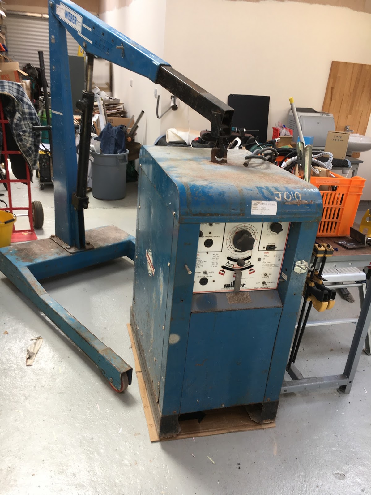
So today it was time to flash up the TIG welder. This is an ancient (older than the MIG) Miller-Interlas AC-DC machine, model 320ABP. This is capable of something like 20 - 300A in 3 ranges, with built-in HF, post gas timer, remote contactor and current control etc etc. In its day it was a fine machine but weighs almost 1/2 tonne, so is a bit dated and unwieldy compared to an equivalent inverter machine. It took me a while to manoeuvre it into place.
Mine's a European (Italian made) machine, probably from the 1970s. I knew the guy who bought it new and rescued it from the scrap man. I changed a tiny bridge rectifier in the control circuit and brought it back to life again. It was nicknamed "Bertha" apparently and was one of 3. Here are a couple of pics taken with the top off while I wired it up. It's all made up with cables and plates and bolts....


As a power electronics engineer, this is an interesting machine. It's basically a 50Hz switched-mode power supply, about the simplest possible implementation, yet capable of good control. It has a giant single phase transformer (reduces the 240V down to something like 60V), 2 massive magnetic amplifiers and an equally massive output inductor. The mag amps allow the output current to be controlled by a small (10A) DC current, with the only large semiconductors being 4 massive (200A) stud diodes.

The HF circuit generates the starting voltage by means of 2 large spark gaps and a high voltage transformer (2kV? I forget), coupling into the output by means of a pair of mica capacitors and a large air-cooled 1:1 transformer.
First I had to finish wiring up the 63A feed from the consumer unit. I had planned 3 outlets but will only need one for now. I fitted an ABB 32A socket with disconnector, then rewired the welder with a European 32A blue (single phase) plug to replace the US cooker plug I was using in Canada.


Job done. The welder powers up and makes all the right noises.
Like many mains transformers, this was prone to tripping the circuit breaker periodically, despite having fitted a 63A Type C MCB at one point. In fact, the cause is saturation of the cores due to remanence ie residual ("remaining") magnetic field in the cores at the moment the mains was disconnected (eg contactor opened). If there is sufficient remanence and you then come along with the correct instantaneous polarity (and duration) when you next connect the mains, you can get an additive effect resulting in sufficient net volt-seconds to saturate the cores. When that happens, the instantaneous (short circuit) current is enough to trip almost any MCB you care to fit and the only cure is a soft starter. One thing you can deduce from this is that most mains transformers actually run a pretty high magnetisation current / peak flux, presumably more than 50% of Bsat. The core losses are obviously not a limiting factor.
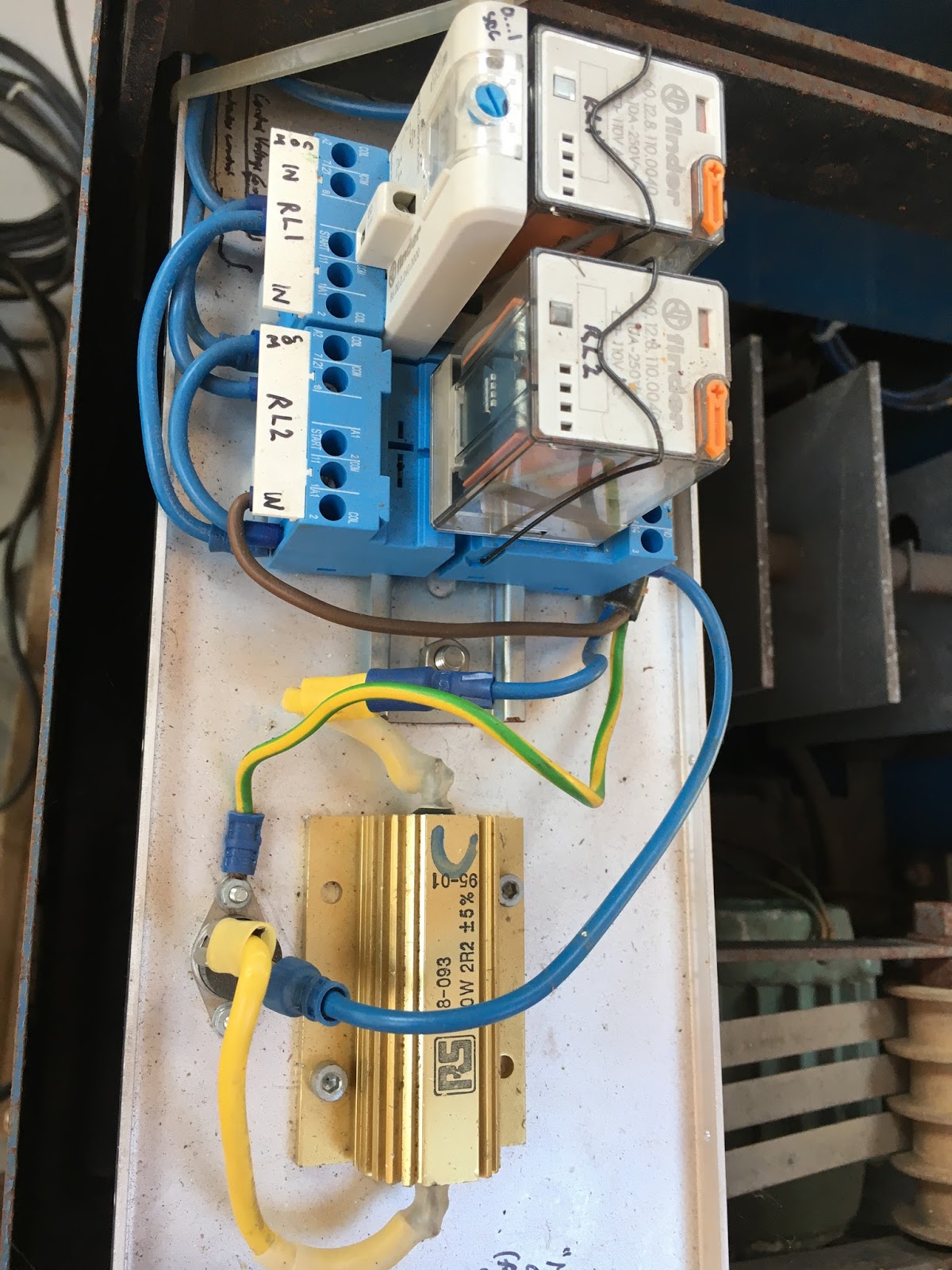
The best soft starter to use is probably a phase control (SCR or triac) that will progressively energise the transformer up to full voltage over a period of a few hundred milliseconds. But these are proper expensive. A perfectly adequate alternative that costs a lot less is a simple time delay relay with a series resistor. This prevents the main contactor closing until the mag current has been stabilised. The resistor value is actually quite critical though - too small and you will still be able to saturate the transformer and barely limit the fault current. Too high and you won't establish (and centralise) the magnetisation current. For this transformer, I found 22 Ohms to be close to optimal.


But the spark gaps were clagged up with some sort of gunge. God knows where it came from but it didn't look too clever. I whipped them out, scraped and honed them with a diamond sharpener and put back together. Sorted - spark gaps working again.


Finally, connected up the home made foot pedal and the gas feed, taking care to anchor the bottle to the machine so it can't be knocked over easily. It all seems to be working, although I needed to oil up the massive range and polarity selection switches before I could move them with herniating.
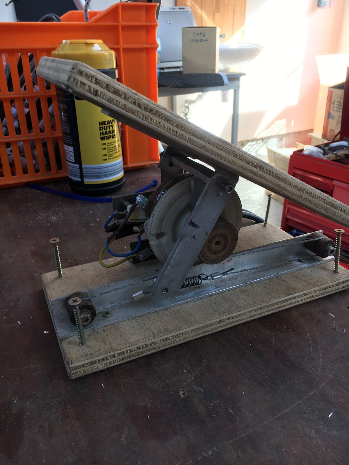
A genuine Miller foot pedal for one of these is stortionate, so I had no choice but to make my own. Originally I used a small pot on the torch to control a cheap bench PSU and thus generate the control current. It worked OK but after a while I reverted to good old fashioned wire wound technology. For one thing, I had enough of a challenge juggling the torch and rods without also trying to control the current.
I was able to find a high power rheostat from Farnell that fitted the bill and figured out a way to lash it up to a foot pedal. Ideally I'd have made a more substantial metal frame or housing but the plan was to make the machine usable rather than create a work of art. As well as housing the rheostat, it also incorporates the contactor control (micro)switch.

I need to check that the current control ranges are what they should be but I seem to have a goer for now.


No comments:
Post a Comment