The X axis gib is easy to adjust. There's a 13mm bolt on the end of the ballscrew, accessible from the LH side of the machine. So it's easy enough to use a crank handle and long extension from a socket set to turn the ballscrew back and forth, then gradually tighten the gib until it starts to bite. Interestingly, at that point, if you move the table with the RH gib screw removed, the gib can self-tighten and make the servo bomb out. So it's necessary to loosen off the RH screw 1/8 of a turn at a time, then tighten the LH (tightening) screw. You can feel the gib nip up to the RH screw - and finally, after enough tightening, the ballscrew starts to tighten.
So I consider it done for now. The backlash is certainly better now and it is what it is. I'll measure it again in a few days and live with what I find.
Yet another job that's been stuck on the list is repairing the autolube pipe in the head. There are various pipes that come from the lube pump to the knee and head - and from there to the individual lube points. Somehow it got torn off, presumably when I was crudely ripping out some of the old cables. The bummer is that access to the broken section is almost impossible. Almost but not completely. I can just see the end of the torn pipe and just reach it with my fingers. It's peeking around the corner at the top left, just above the compression fitting.
It's pretty tight, so I ended up removing the bottom microswitch and the lube pipe feed that feeds the RH side of the quill.
When John Gunn was kind enough to give me some olives and nuts for the power drawbar air lines, he also enclosed a quick fit coupling for 3mm / eighth inch pipe. If I can chop off the end of the torn pipe cleanly and get my fist of ham into the confined space, I should be able to make a successful connection with the quick fit coupling. I then only have to feed the repaired pipe back through the cavity in the head and ram and connect it back to the lube pump, then the job is done.
Managed to get some Lindstrom cutters in and develop enough leverage ("leeverage", not "levverage", as we are in the UK) to cut the pipe cleanly. Then push the connector onto the pipe end. The end of the pipe was nicely stretched. God knows what I was thinking when I ripped it out. I'm lucky it failed as it did, rather than at the compression joint further out of grasp.
Taped the pipe to a length of brass rod and managed to push it through the ram cavity. Luckily the pipe is still long enough to reach the compression fitting next to the pump. Job done!
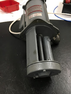
Final task for the day is to take a look at the coolant pump. It's a 220V 3-phase motor and I don't want to cough up for an inverter just for this function. And obviously, I can't simply connect it across the spindle motor due to the very wide speed range. I'd really like to be able to operate it from single phase by using a capacitor to generate the 3rd phase. It's unlikely to be able to perform as well as it would if it were operating from 3-phase but it seems to be a common technique and is worth looking in to.
The pump looks to be in good condition and spins easily. It's a simple centrifugal pump, which is typical for this application.
Need to do some internetting to work out what is required....
Retrofitting 1983 Shizuoka AN-SB CNC milling machine, Bridgeport mill, Colchester Bantam lathe and 1982 Tree UP-1000 CNC lathe with modern controls - and other workshop stuff
Subscribe to:
Post Comments (Atom)
End stop for drawer self closing damper
Que? We have a couple of these pull out spice drawers in the kitchen. They are 150mm / 6" width and are basically filling in a 30cm gap...

-
Setting up the servo tuning(?) software: Having spent a couple of hours yesterday pratting about with the PID controllers for the X and Z ax...
-
Right, so having gone through the motions with the X axis (cross slide), I should now be able to set up the Z axis (longitudinal) encoder an...
-
The bearing arrived as expected this morning. Took a few minutes to make up a 42 x 25.5 x 7mm thrust washer, then fitted the bearing and was...


No comments:
Post a Comment