In September last year I bought a few BT40 toolholders from John Stevenson, as he was downsizing his workshop in anticipation of retirement. Although my machine is INT40 (aka NT40 and ISO40), it's possible to use BT40 if you weld(!) a shank onto the end of the taper, as I demonstrated a week or so ago.
When I was there, we obviously had a cup of his special coffee and nattered for a while about workshop stuff. He'd offered me a home-made 4th Axis he'd made some time ago for his Beaver CNC milling machine. It was in a bit of a state and he offered it to me for free to a good home. It would have been rude not to have accepted the generous offer, so we somehow managed to dump it in the back of my car.
It's been sitting in the corner of my workshop for a while now, asking to be looked at. My Newker CNC controller has 4 axes, as I planned to acquire or make a 4th axis at some point. So the stars seemed to have aligned on this one.
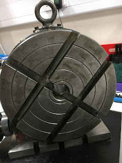
It's bloody heavy, being composed of a 10" rotary table, an adaptor plate, a 3-jaw chuck, a welded up bracket and a massive stepper motor. When reassembled, the table is driven by a toothed belt (missing) which is protected by a fabricated cover. This is the main lump (ie less the motor and cover):
There was a bit of backlash between the input (worm gear) and the table (worm wheel) and although it wasn't bad at all, this seemed like the time to adjust it the best I could. The only experience I have of RTs is through the Chinese Vertex clone I bought a few years back. On that design, the input worm is mounted on an eccentric body, so it's quick and easy to rotate that to adjust the backlash. On this one, there was clearly a different means of adjustment.
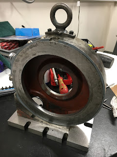
In fact, there's a funny long bracket / body that is held in place by 4 bolts. There's enough slop in those counterbored holes to allow some adjustment. What's not immediately obvious unless you look for it is the adjuster that pushes the worm gear assembly into the worm wheel. This is the funny worm gear bracket:
It's starting to clean up nicely, with WD40, green pot scrubbers and lots of kitchen paper:
If you look carefully, you can see the adjuster pillar that pushes the worm gear to adjust the backlash. You can adjust this using an Allen key inserted through a hole in the mounting foot:
The worm wheel and table look to be in very good condition. It's obviously a good quality table and has had little use:
I'm pretty certain that John hacked off the bolt slots in the top of the table and ground them off. And at the base, it looks as if the piece of gauge plate substitutes for the original cast slots:
This is the worm gear and its funny bracket. No wear to speak of:
Here we are, all back together again:
I've fitted 3 bolts to fill the open holes. They were for the original lifting eye (2 x M8) and the table lock (M10). Job done - all greased up and reassembled!
Now for the ancient chuck. It's had a hard life:
Look at the state of that!
All cleaned up and degreased with WD40 and Gunk (washable degreaser):
Partially reassembled and regreased:
Loosen up the grime on the stepper motor:
I already have some "L" series belts for the Bridgeport conversion. This confirms that the belt is an L sized pitch but it needs to be shorter than these:
I piece of Velcro-type cable tie material gives a pretty good estimate of the required belt size:
I've ordered a 20mm wide "L" pitch belt from Beltingonline, who I've used before. It's clear that the next standard size up from my estimate is 476mm length. I readjusted the green thing and it looks as if that should be fine. In old money it's a "187L", which I assume denotes that it is 18.7 inches. That's 50 teeth at 3/8" pitch which seems about right - it would be 18.75" to be exact.
Silicone sealant to fill the hole where there was probably once some form of gasket:
This is the original cover, engraved with John's handiwork:
And the 3-jaw chuck, reunited with the backplate. Still pretty well worn out but at least it's clean inside and out - and greased up.
I've ordered a Leadshine DM556 (50V, 5.6A) stepper driver from China (£38). Whether or not it is a genuine one or a copy won't be clear until I get my hands on it, but I'm hoping it will be a good copy if it isn't pukka. Or good enough. A genuine one from Leadshine is about £80.
There.


No comments:
Post a Comment