Although we can't get McMaster Carr stuff in the UK (nor could we in Canada when I lived there), it's less hit and miss than the likes of Traceparts, as all the parts are available in a consistent, common interface and the range of parts is quite amazing. Traceparts has a larger inventory but they are all hosted by different manufacturers, so there is little consistency. It can be pretty frustrating to use that system to try to find simple parts such as fasteners, so MMC is the way.
There's a simple interface within Fusion 360 for opening the MMC online catalog and bringing CAD models into your design under the Insert menu. This way I was able to insert the 8 fasteners and the hose coupling to complete the assembly. I also changed the thread on the push rod to a modelled one just for appearances.


Making the pillars:
So the last items to make are the pillars that hold them end plate together. These are made from some mystery alloy rod of about 16mm diameter, 34mm long, with reduced (10mm dia) ends to locate in the end plates. Tapped M8 at each end.

They seem to fit


Reasonably accurate, given the context:


I done got me some o-ring material some years back. It's what I designed the groove dimensions for but needs to be cut to length and superglued together.

Looks OK

All assembled, just requiring the bottom plate:

There:

This is where it will go. The existing arrangement relied on backing the quill up against this adjustable stop, which forced the drawbar down against the yellow die spring, releasing the pullstud.

Here are the solenoid parts.
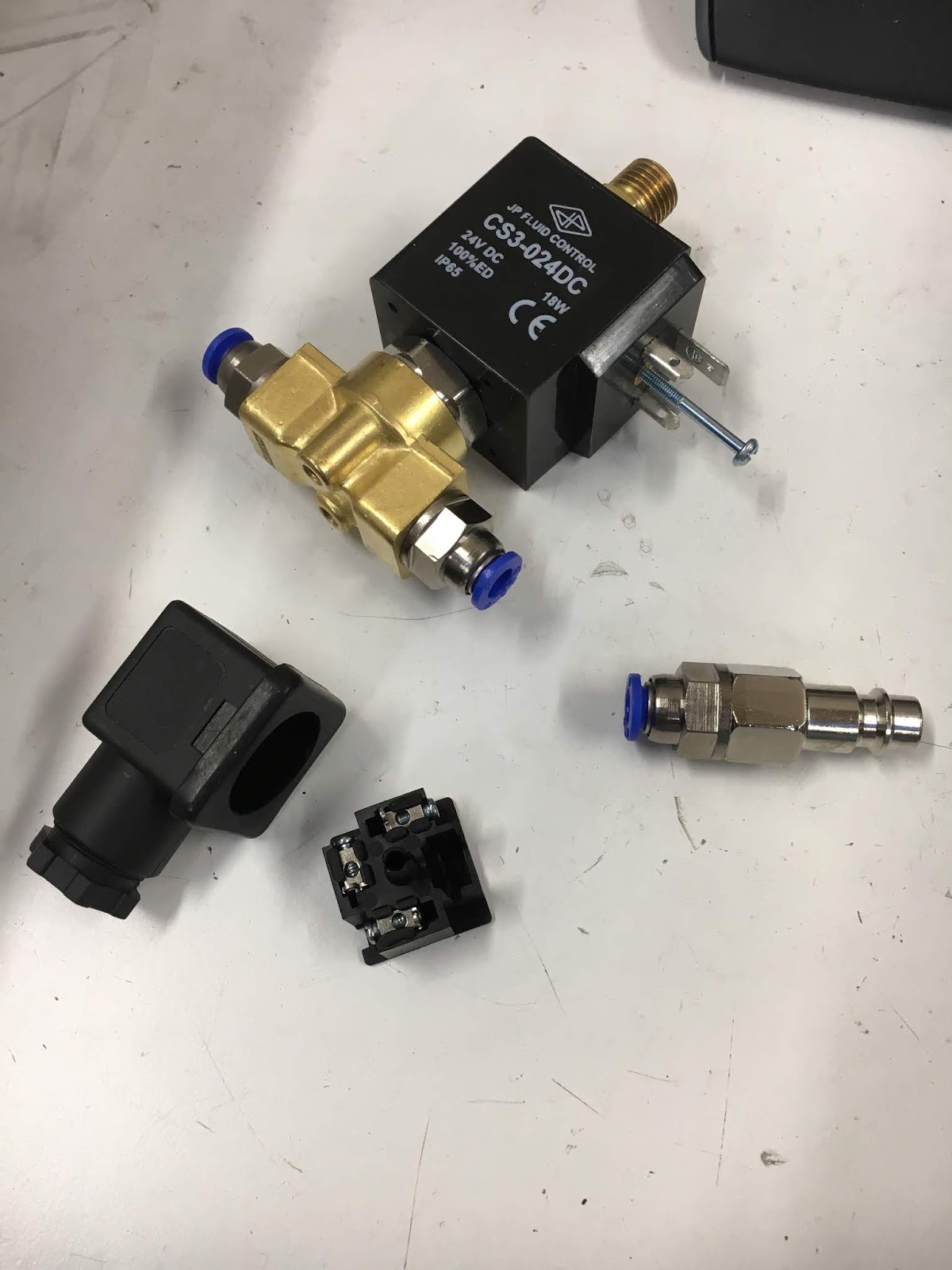
I've wired a flywheel diode into the back of the solenoid plug:

Taking the piston out shows the issue - the rubbery seal thing has a crack on its surface. It doesn't look central enough to be an issue but the piston is a pretty loose fit and presumably allows enough radial movement for the crack to coincide with the seat. The annular indentation is almost certainly a moulded feature, as the return spring is very weak.
Spoke to Tameson customer services, who have sent a replacement piston. I can still get the drawbar mechanism installed and commissioned regardless, as the thing still works and the piston can be changed easily without disturbing the rest of the installation.


Here it is, perched on top of the machine. Not the most professional work I've done but it performs the required function and seems to validate my design calculations. There's a career as a machine designer in me yet.....

Good stuff. With the SSR relay wired up to the M10 (chuck) output, I can toggle the drawbar up and down from the front panel. Sorted! No detectable leakage when the piston is actuated.
Perhaps now I can look forward to cutting my first swarf on the new addition to my CNC workshop.


No comments:
Post a Comment