I was trying to keep the concept simple to avoid messy machining and structurally weak parts. This was complicated by the fact that the spring is about 48mm OD and the seal is 50mm ID.
The solution was pretty obvious although I'd left it in the hands of The Stupid Fat Bloke, which is always a mistake. With him kicked aside, I could see that the seal retaining ring can also act as the spring guide. That made matters fairly straightforward, so I was finally able to get things moving on the machining front.
Here's what the piston assembly looks like. Results in a simple piston, a simple seal retainer and I can use my existing spring. The piston nose bottoms out on the end plate of the cylinder housing, preventing the spring being squashed or the cap head screws digging into the housing.


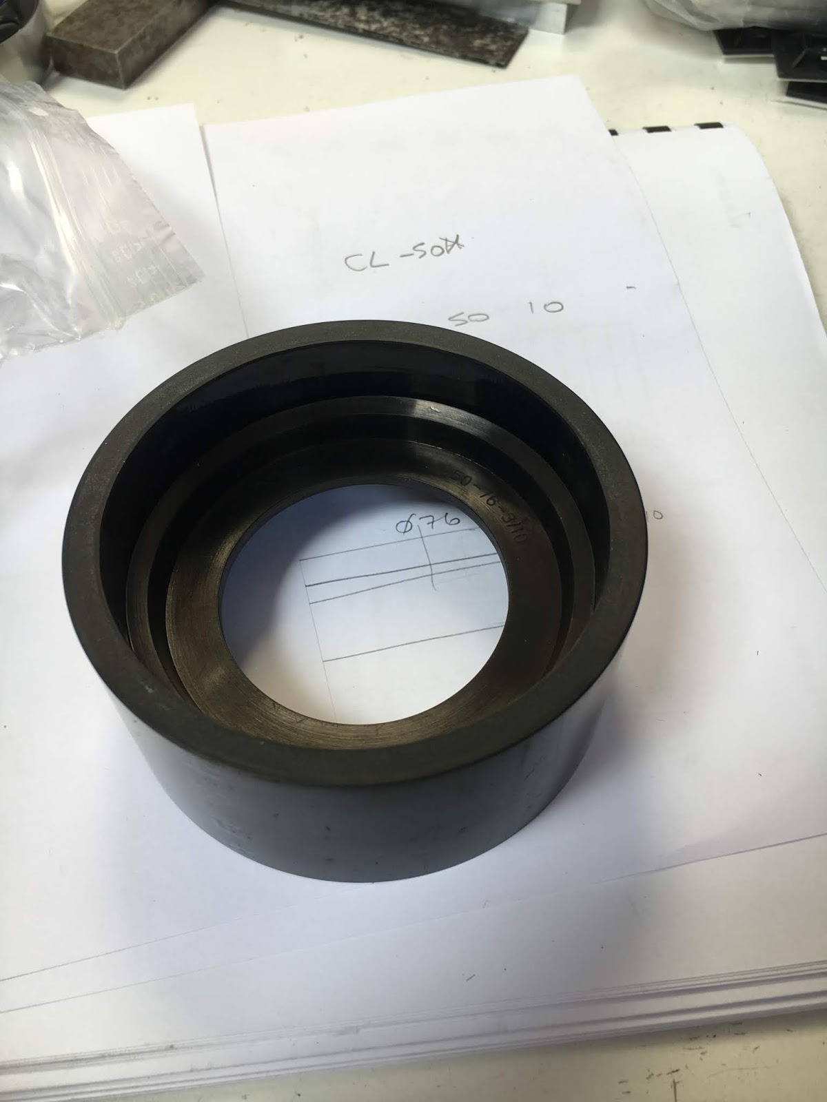
All the shit I'd ordered turned up during the week. Here's the seal, sitting in the cylinder. It's possibly a bit small on the OD but should work. The technical drawing(?) was very basic....
The solenoid valve and various BSPP fittings:

Looks like this when you assemble the various parts:

BSPP taps - 1/8" and 1/4" sizes, for the air hose fittings:

I also found the bag the original die spring came in. Seems it's actually 520lb/in, so I may need to reduce the preload....


M12 tapping:

Reduce the nose to the right length:

Turn it around and face off the piston face:

Machine the step with a parting tool:

Chamfer:

Done:

Piston retainer will need to be made from steel as I have nothing suitable in loominum. But this hollow (mystery metal) bar stock is a handy starter:


Parting off under power feed:


Done:


Looking good:

Next - drill and tap the ring and piston (and seal) for the four M5 retaining bolts to complete the piston assembly, then move on to the housing end plates...
Quickest to simply use the MPG to "manually" operate The Shiz for this.
First, the retainer ring. A v-block and parallels to hold it in position:

The 41.44mm dimension works best - results in +/- 20.72mm for X and Y coordinates:


Then the piston:

I used the probe to find the centre of both parts, then MDI to set the X and Y positions of the holes:


Now for some holes in the seal. This is better for making disks than for making holes:

This works better for small holes:

Done:


Piston assembly completed:

Still fits the cylinder!

Next - focus on the end plates...


No comments:
Post a Comment