First, order up some pneumatic fittings. I struggled to get my hands on suitable fittings when I was connecting up the drawbar and gear selection solenoids on The Shiz, so I've established that I don't have any suitable bits and pieces. Let's order up a few parts:
Pneumatic solenoid valve:
I need a "3/2-way" valve so that I can blow air into the piston, then allow the piston to return by exhausting the air back through the valve to the atmosphere like this:

Something like this would do:

Push-in hose fittings:
And some 1/8" and 1/4" BSPP push-fit connectors. These are the 1/8" ones. The 1/8" dimension refers to the threaded end and the hose diameter is the 6mm bit. Obviously got some 6mm hose coming too...

BSPP taps:
I don't have any suitable taps for BSPP (parallel pipe thread), so I've ordered up some 1/4" and 1/8" ones:

Pneumatic seal:
I doubt a std o-ring would work out very well in this application, so instead, I'll get a couple of these bad boys which are proper lip seals, designed for pneumatic applications. The price doesn't seem silly, although it's almost doubled by the time you unclude shipping from Froggieland.
Pneumatic seal CL-50X76X10-NBR90 - 50x76x10 mm
Return spring:
The spring gods were with me. I managed to unearth a couple of spring samples I'd acquired during the course of a previous job where we made springs, amongst other components. This one looks pretty suitable for this application:

- 46mm free length
- 14mm solid length (compressed until all coils are touching)
- 48mm outer diameter
- 2.8mm wire diameter
- Looks like stainless, likely 17-7 PH
- ~80N load at full compression (spring rate = ~2.5N/mm)
- Closed and ground ends
That looks reasonably workable. Modelled it up:

Refining the concept:
I like to spend a little time refining a concept before launching into the machining bit. Although it's nice to make progress on the swarf front, I like to convince myself that it will work and also minimise the effort required.
Here are my first 2 attempts to clarify some of the details, now that I know what the seal and spring look like:
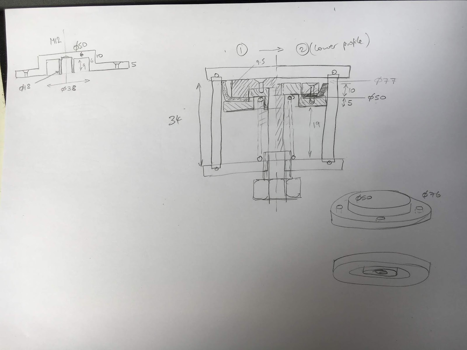
The piston would look like this:

That concept is on the left of the sketch ("1").
Option 1.2:
This evolved into what is shown on the RHS of the same sketch ("2"), as I need to minimise the total height buildup within the piston.

Option 2:
This may be better:
- Reasonably simple piston design
- Grooves for spring location
- Clamp ring to hold seal in place. Arguably better to have the clamp ring on the top - I may still swap them over. Not decided yet.

I'll weigh up the 2 options and then model up the winner. I feel I'm sort of moving towards option 1.2....


No comments:
Post a Comment