Yet another mouse accident / finger twitch inflicted me last weekend when innocently surfing the Centroid Acorn user forum. I need to find out what is causing this before the Domestic Manager twigs what is going on.
This time, I came home 5 days later to find a parcel outside the back door with some stuff from Centroid in the US.
This is the much-awaited Acorn expansion board, aka "ETHER1616".
What's an ETHER1616?
It's an expansion board, aiming to improve on the rather limited IO (8 inputs and 8 outputs) of the basic Acorn board, so-called because it is connected to the Acorn by Ethernet and provides an additional 16 inputs and 16 outputs. Up to 3 boards can be connected up simultaneously, providing up to 48 inputs and outputs. The IO are all optically isolated from the main controller.
ETHER1616 setup guide.
In fact, the expansion kit includes 3 PCBAs, namely the main motherboard and 2 relay boards. The relay boards connect to the motherboard using (supplied) IDC cables. There's also a dedicated PSU (from Meanwell), a TP-Link 10/100 Ethernet switch and some shielded Ethernet cables, plus a few bits and pieces in a bag, which turn out to be a choice of plug-in SIP resistor arrays for input pull-up / pulldown, depending on the system voltage you are using (12V, 24V etc).
Taking a closer look at the motherboard:
Like the Acorn boards themselves, it seems the connector headers have been hand soldered, presumably by Centroid in the US. This leaves flux residues, so clearly it's not no-clean flux and they haven't seen fit to clean the boards afterwards. Not the end of the world (that's next week) but I prefer to see this cleaned off myself.
Overall it looks pretty well executed. The green edge connectors are 2 piece pluggable jobbies, so you can remove the board without having to unscrew all the terminal connections. The white connectors are for the relay board connections. There's a 7 segment LED display and some sort of programming / debug edge connector that I assume we won't be using.
What's on the motherboard?
A Microchip PIC32MX350F256L 32-bit micro. Seems a bit OTT?:
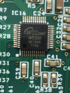
Closer view of the Ethernet controller:

And here's a closer look at that DC-DC. Generates 3.3V from 7-28V input. As there are only 3 pins, it's clearly a non-isolating buck (down)converter.
The SN65C3222 line driver receiver runs what is described as "SERIAL 1" but doesn't seem to be used in a user setup. Perhaps it allows board testing without the need for a network (Ethernet) connection. Can't be bothered to trace the path to see what it connects to but you might expect the PIC to be involved.
These devices are ACPL-244 opto isolators for the various IO signals
This is the connector for one of the relay boards, next to some MC74AC125 tri-state quad buffers
Yet another Recom DC-DC module - there are 3 of them in total. Presumably not a cheap solution but simplifies the design process. They are pin compatible with the 78xx linear regulators but being switchers, they aren't anything like as lossy (hot). This one outputs 5V at 1A. Farnell pricing is around £2.50 each in 250 qties.
This is a 25AA02E48 (2kb serial) EEPROM from Microchip. Seems to be associated with the Ethernet driver but not sure why, as the W5500 app notes don't show the need for one.
The edge connector is presumably for talking to the PIC during s/w development. And here's the Microchip serial EEPROM again.
Tested 5th November 2019 (Bonfire Night!). Hope that's not a bad omen...
...to follow...


No comments:
Post a Comment