Various electrical bits remain to be fitted under the cross slide.

- The encoder read head, magnetic strip and encoder cable fit one one side of the cavity (double red dots).
- On the other side is the +limit / home switch and -limit switch (single red dots).
Cross slide encoder:
Let's get the linear encoder fitted. Here's the Machine-DRO datasheet for the mini encoder. Not impressed that they can't even get the drawing right. My encoder head has mounting holes in the wrong place - "wrong" if you consider the datasheet to be "right".

Even a blind fool can see that the datasheet doesn't reflect the reality of what they are supplying.
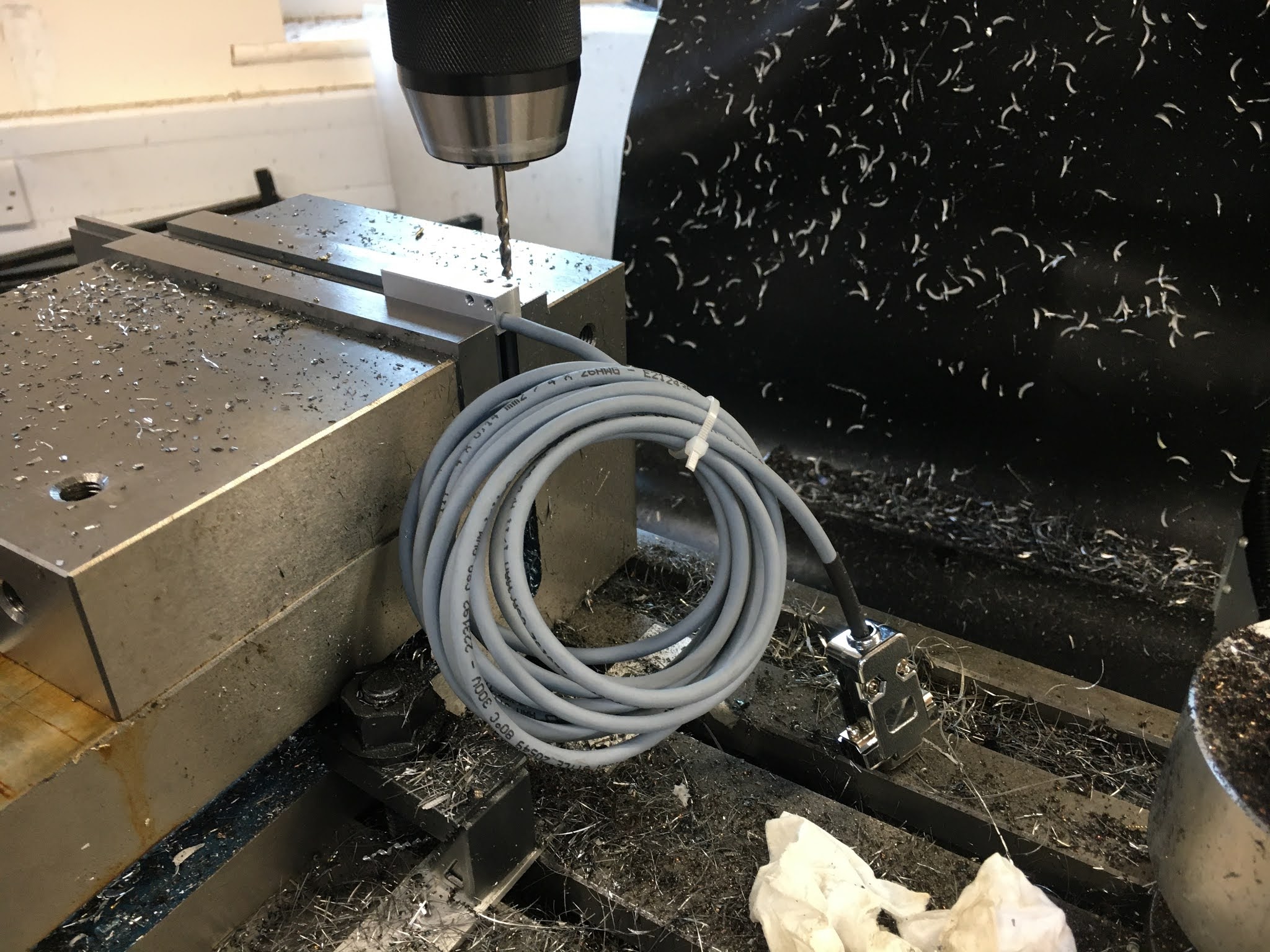
Luckily I noticed this before I created the CAD model, so the tapped holes in the saddle body are in the right places. But now I need to drill out the fixing holes so they are M3 clear rather than M3 tapped.
3.5mm drill, placed with the touch probe and DRO:

Limit switches:


Looking good. Even better - they fit perfectly.

That's the cross slide gubbins done for now.


No comments:
Post a Comment