Let's get busy machining stuff:
Here's what I need the ballscrew to look like:

So firstly, chop off the excess length and face off / turn down.

Both ends done - coupling at one end, bearing and pulley at the other

Now make up a locknut with M10 x 1.0 thread. I have some nice 1" bronze, so why not use it? Nice to machine and very colourful!
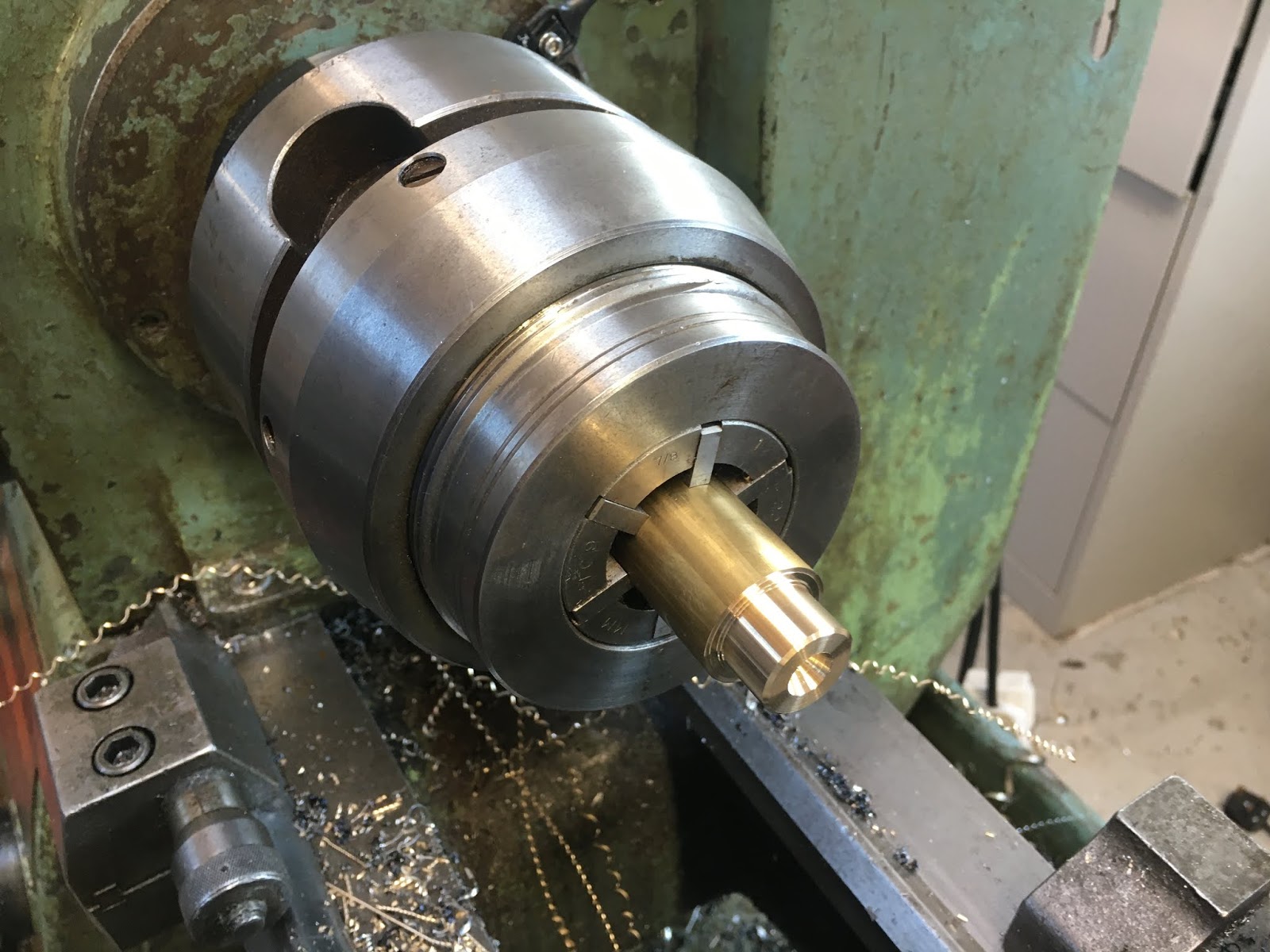
The tap is clearly nice and sharp....

Nearly done. I need to drill a couple of holes in the nut so I can use circlip pliers to tighten it. I'll do that in the mill later when it's next in use.

So that's the ballscrew pretty much ready to slot in. I'm thinking that I will drive the ballscrew via the coupling with a piece of 8mm rod initially, to avoid having to butcher the original leadscrew until it's absolutely necessary - or even at all. Something to think about....
Machining the underside of the cross slide body:
Let's prepare for machining the underside of the cross slide now. I'm almost at the point of replacing the leadscrew with the ballnut but first I have a few mm to remove from the underside of the cross slide, to make room for the ballnut yoke, the encoder read head and the limit switches. Also, I need to machine the fixing holes for the ballnut yoke (M5 clear, with plenty of rattle). Although it would still be possible to use the original leadscrew and nut at that point, I'd need to pack the nut out to do so.
Let's double check the dimensions, particularly the required height of the underside relative to the ballscrew centreline. If I got this wrong, the ballnut won't be at the correct height for the ballscrew and I'd have to bugger about with packing or machine some more off the yoke, depending which way I erred.
Design height:
In Fusion, I see the centre height of the ballscrew above the slide surface of 6.36mm.

Now I need top check the ballnut yoke height vs the dovetails in the cross slide body.

The channel is 25.4mm (1") wide and the ballnut yoke is 28.5mm wide, so I need to machine a shoulder on each side, of 1.55mm width with enough depth to clear the adjacent lands ie ~1.5mm. That's a pretty trivial mod and means I can refit the original leadscrew nut at a later date without messing about - there's no point of no return.


So:
- Machine shoulders at either side of the yoke: >1.5mm depth, leaving 25.4mm width.
- Machine the underside of the cross slide body.
- Drill and counterbore the yoke fixing holes. These are now M5 fixings - originally showed M4 which are a bit spindly, yet there's room for larger jobbies.
Sacrilege time:
This is a lot less significant as surgery goes, compared to the butchery I perpetrated on the saddle.
Pleasingly, Tim Paterson's post processor add-in worked splendidly and although there was no tool change, it handled the replacement of the rapid feeds nicely.
Slight problem-ette, though. Half way through the operation (one side done), the machine stopped and refused to resume, claiming an e-stop situation. Bugger. At least it simply came to a halt with no harm done.

In fact, with the table in the middle of its envelope and the actual e-stop clearly not depressed, there wasn't a "real" e-stop at all. But on this machine the limit switches are on the same input as the e-stop, so more likely was that they were the root cause. Annoyingly, I'd forgotten to tell the tool library that the BAP300 tool would be cutting dry, so the coolant came on and the tap wouldn't completely stop the flow. The Y axis limit / home switch assembly is in this little box under the saddle and sure enough, when I loosened the screws on the cover, it was clearly full of coolant.

It's obviously getting in through the top. I'd seen previously that it was full of neat oil but couldn't tell if that was coolant or lubricant, not least because the previous owner had only ever used neat oil.
Anyway, dried it out and machined a slot in the cover to enable the egress of any further further ingress.

And back into action. Finally for the cross slide, I needed to counterbore the yoke fixings:


Hi Murray! Love the great content here. Been reading now for several days on your conversion and what a spectacular job you did. I've recently acquired a Shizoka AN-S and have been cleaning for what seems like a month now. I've finally gotten in the electronics and the servos and am machining new motor mounts. My Y axis (short) has zero backlash on the ballscrew, however my X axis (long) is showing some slop before the table starts to move. I'm turning everything just by hand. I am wondering if this equates to having to replace that screw or is there any adjustment to tighten it up? I'm asking because if I need to replace it Id just as soon order it now and get tearing it apart. Since you did yours from the ground up I was hoping you could provide some insight if theres any adjustment.
ReplyDeleteThanks again if you can provide any info.
AL
Hi AL
ReplyDeleteGreat to hear from a fellow Shiz user!
This was an area I spent a lot of time looking into. The ballscrews on mine are from HSK and very high quality - I expect same with yours. I used a DTI to work out where it was all coming from and it was due to a stackup of several factors.
The thrust bearings were not in a good state. These are fairly standard items, so it was a simple matter to get replacements of a decent quality. The other thing I looked at was the adjustments of the gibs. At least on the X axis there's only one but for the knee and Y axis there are several each.
I didn't fancy removing the table on mine, as it is massive. Also mine's actually an AN-SB which means the ballscrew doesn't move with the table. However, my machine is now pretty good with the new bearings.
BTW, if you want a set of section drawings and parts lists, I scanned mine and you can find them on Yeltrow's website https://sites.google.com/site/yeltrow/shizuoka-an-s-mill-linuxcnc-conversion
Where are you? I'm in the UK as you might have guessed.
email me on murray.edington@gmail.com