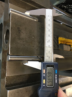
Before putting my saddle under the knife, it seemed a good idea to check the dimensions, otherwise I may end up butchering the saddle and finding I've screwed up on the basic positioning of the features. My design is only as good as the model I've made which in turn are based on some measurements I made a few weeks back. So first, let's do some sanity checks, particularly of the positioning of the cavity / channel that houses the leadscrew-cum-ballscrew.
Ooops. I see that the bore for the leadscrew isn't actually central between the dovetails. That was clearly an assumption I'd made when creating the sketches that defined the saddle body. It's off by somewhere between 1 - 2mm. That could be enough to fuck things up in a bad way.
My newly machined bracket would fit OK but the front ballscrew coupling and the rear bearing would have been correspondingly misaligned. I'd also have machined away too much of one wall and not enough of the other.
Measuring it up:
Simple enough to realign the various features but first I need to know how much off I was. Time for some reasonably precise measurements. Reasonably means "within a few tenths" - but in this case I'm talking mm, not thousandths. No need to get my willy out to wave it about. Remember, I have about 1mm of slop in the mounts at the bearing end.
Dovetails - best measured from the ground (angled) surfaces, rather than the rough corner edges:
Rather than try to do a load of fag packet calcs, it's easier to create a sketch in Fusion and use that to determine the offset distance, then go back into the CAD model sketch and correct the dimensions. The regenerate the assembly and rerun the CAM.
Dimensioning sketch:
Here we are - the yellow dimension is the required offset. In other words, that's the error I'd built in by assuming the leadscrew is at the middle of the dovetails. Easy mistake to make...
Well caught, fatty!


No comments:
Post a Comment