Firstly, the plate around the spindle needs to be cleaned up and fitted.

A bit of WD40 and a white pot scrubber does the trick.

And some hybrid adhesive sealer to fill the gap and hold it in place.

There are four M6 holes under the spindle nose These are good for holding it in place.

There's a slight gap, perhaps due to the draft angle of the casting or simply distortion of the plate.

Needs holding in place while it cures

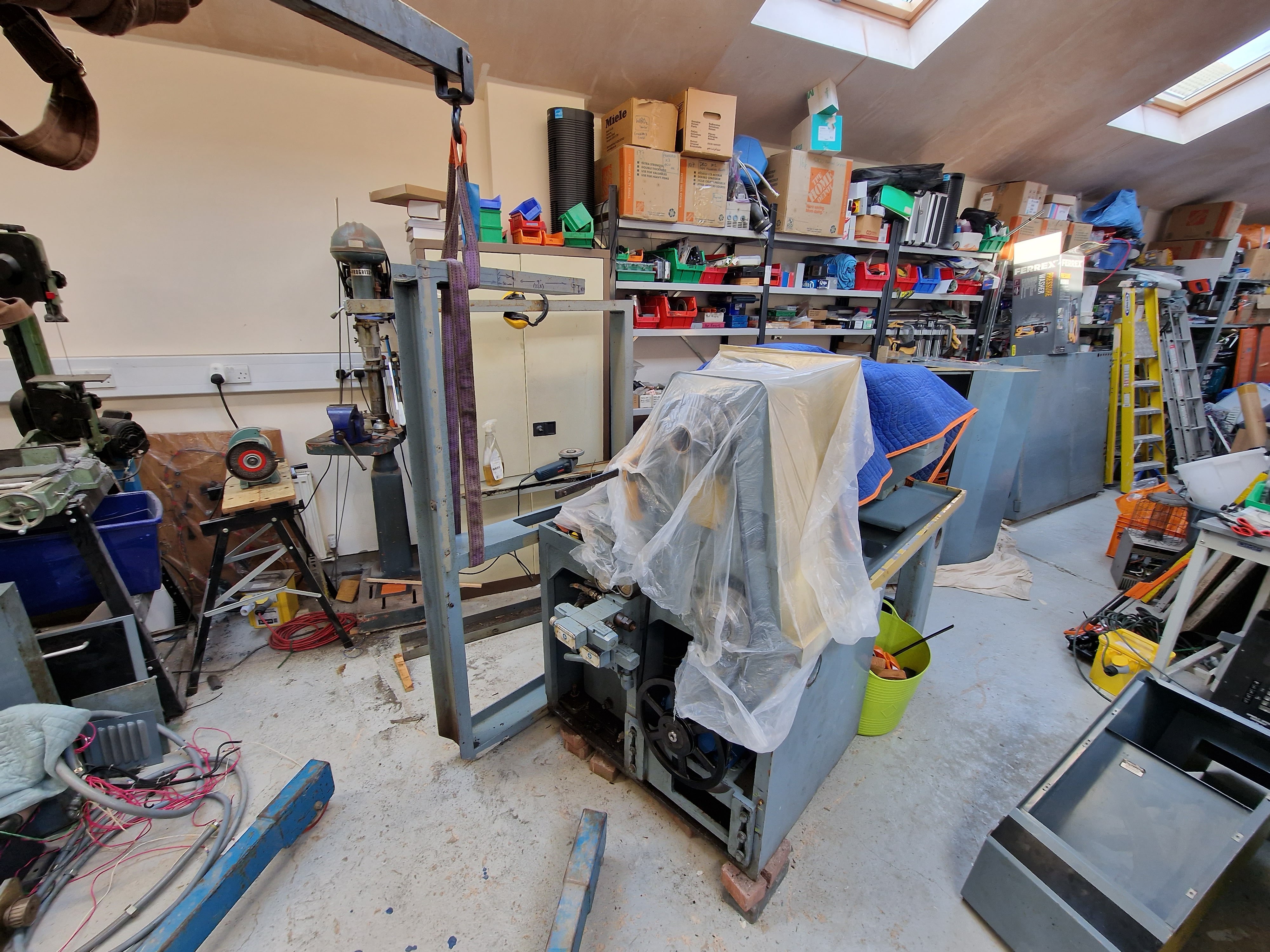
Now for some angle grinder action. First, cover everything with dust sheets.


Then mark out the frame, earmuffs on and set to it.

There was a lot of stress in the frame, so when I cut the meddle member, it sprung apart.

Finally - nobody died and no broken disks.

It cleans up with WD40 nicely.

The engine crane is handy here for holding the framework in position.

One of the crucial bolts was snapped off, so a cutting disk in the angle grinder came to the rescue.

There we go. Looks a bit odd but should do the trick.

Lets offer up the headstock cover.

Looks workable.


I need to add a couple of fixings at the foot of the housing.

Like this

And a couple of M6 holes for the fixings.

There.


Now I need to figure out where the various compts will fit and how I'll wire them up.


No comments:
Post a Comment