Monday, 30 May 2022

Hydraulic pump commissioning - striking oil!!

Having got the spindle running and not being quite certain I want to tear the spindle apart again (yet?), I'll move on for now. 

Next on the list is the hydraulic pump which will be needed to operate the turret and the tailstock. I've wired up the Yaskawa drive (1.5kW GA500) and so far I've managed to have wired up most of the control, so there's a chance it will simply work when I power it up.

Obvs I don't want to crank it up to full speed on a completely untested machine, so I will start at a low speed and see what happens. For one thing, there's a 50% chance it will rotate backwards. That should simply drive air back through the oil pickup - hardly the end of the world.

Yaskawa DriveWizard Industrial:

Previously I installed and tried out the DriveWizard smartphone app which connects via USB On The Go (OTG). Or it's supposed to. I coughed up (about £3) for an OTG adaptor to plug the slave end of a std USB cable into the GA500 so that the app could use the smartphone as a USB host. That turned out to be a waste of time and money, as it refused to find the drive. Bizarrely for a new product, the GA500 has a mini USB connector - I'd have expected a micro USB perhaps but hey, at least I have a wide selection of cables to choose from.

DriveWizard Industrial is a PC program that uses a more conventional USB cable to talk to the GA500. The GA500 is the slave and the PC is the host - very conventional. Furthermore, it actually seems to work. There's a setup wizard that will run you through the basic configuration but when I checked the default parameters, they were pretty much spot on. It had even been configured for 50Hz motors. The motor nameplate parameters are shown in this post from a few weeks back

The operator panel runs from USB power, so you can configure and program the drive without the need to apply mains. Obvs you need to apply mains and enable the drive remotely before anything will move. Once connected up, there's a virtual operator panel that allows you to enable the drive and set the reference frequency. Bizarrely perhaps, this all worked out of the box.

Did it work then, Fatty?

Well yes and no. Initially the motor ran backwards at about 8Hz (around 240rpm) - this was always a 50:50 chance. The bubbling sounds rather gave that away. So instead, I ran the VFD in reverse so that the pump ran in the correct direction. After a short delay, the pump primed and started to build pressure. Then the feed hose started pissing oil out over its entire length, from the pump all the way along the drag chain to the turret. Fuck. So basically the hose(s) are completely perished. 

If you look closely, you can probably see the pools of oil all over the rear of the machine...


...all the way from the pump outlet to the turret.

Luckily I was able to stop the motor quickly and the oil spillage wasn't completely overwhelming. But now I'll need to remove the feed and return hoses and get some new ones made up. Bollocks. I wasn't expecting such a catastrophic failure of a hydraulic hose so hadn't even thought of testing it - compressed air might have shown up the issue. But at least nobody died on this occasion.

Monday, 23 May 2022

Setting up the spindle VFD (noisy bearings!!) - replacing the tensioner bearings

This is the nameplate on the 4kW Chinesium motor. It's a 2 pole / 3000rpm machine and is about the biggest motor you can get for 230V operation. It's no coincidence that the 4kW VFD is also the biggest you can easily get for a single phase 230V input VFD. The original spindle drive was rated around 5HP, so I am not far off meeting / slightly exceeding what was originally fitted.


The Yaskawa GA500 is almost ready to go out of the box. I've even wired up the control IO correctly. Will it simply work? I could just try and find out but I'll enter the correct motor parameters etc and do the job properly by running the autotune feature.


That was pretty simple. The only challenge was figuring out how to start the autotuning process once the basic parameters were set up. The manual somehow overlooked that basic information. For future reference, the autotune menu is selected as "ARUN" and the parameters are the T-XXX set. And to initiate autotuning, you select the last  parameter ("RUN 10") and hit "RUN". Silly me for not being psychic yet.

So the thing pretty worked out of the box, wiring and all. The only minor isse being that the motor spins backwards. No problem, I can simply swap over any 2 of the phase connections, having randomly wired them up. There was a 50-50 chance of being correct and on this occasion I lost.

How does it run, fatty?

Well...... It's not deafening but it's making noises I'd rather not be hearing, not least having dismantled and rebuilt the spindle cartridge without seeing anything obviously wrong.

The tensioner pulley has made a few noises when I've been playing with it and it warms up after 5-10 mins of running. 


It's vaguely possible that this could be a source of noise although I'm not massively hopeful. However, as I bought replacement bearings when I replaced the spindle encoder bearings, now is the time. Of we go...


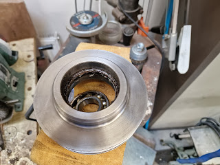
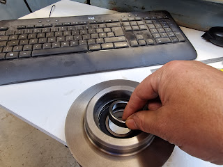
Lots of gungey treacle in there. The outer races are contained by circlips and the inners are clamped against a bush. 


Reay for reassembly.


Don't forget to replace the bush before refitting the second bearing!


There. All back together again.


Well - is that any better?
Hmm. Not really. It's good to have replaced the tensioner bearings but it shouldn't be making the kinds of noise it is. I'll try changing the modulation scheme in the GA500 in case it's some sort of electromagnetically generated noise. Again, I'm not hopeful but I'd rather rule that out before pulling the spindle cartridge out and removing the bearings for inspection and possible replacement.

Saturday, 21 May 2022

Let's commission this mother - OOOF! (trouble with the RCDs and Meanwell PSUs) - WTF????

Let's power this beast up!

My first step in commissioning my current conversion (Tree CNC lathe) failed at the first step and a couple of hours in, I've barely moved forward. I used the 2 Meanwell PSUs that came with the Acorn and the ETHER1616. Here's the datasheet for the LRS-35-24 which is one of them. 

With nothing else connected, closing the isolator trips the 30mA workshop RCD. This happens with either or both PSUs connected up. Lifting either L or N avoids the problem, as does running without the RCD in circuit. WTF???

I ran the machine from a 240-240 isolation transformer (output N connected to GND) with a 30mA RCD, to avoid tripping the workshop supply. Same issue (but different RCD doing the tripping).

There's no measurable path to ground from either L or N in the PSUs using a decent quality DVM, as indeed there shouldn't be. Meanwell claim 300VAC / 5 seconds as well as the normal 85-264VAC input range. There are no TVS / MOVs in the circuit and I assume the X and Y caps are approved parts. WTF??

Operating it at 120VAC input helped a bit but it still tripped out after a few minutes. I reverted to an isolation transformer (with a grounded chassis and neutral) but it's not what I'd want in the final setup. I have a couple of DIN rail Class II PSUs (ie require no protective ground connection) that I could use in place of these enclosed models but it's not something I was planning - or expecting to be required to do.

I measured the mains voltage at between 250-260VAC today. I can't safely measure it with a scope but I get similar results using 2 different DVMs. That's not unusual here these days but as I say, the PSUs are specc'd and tested (not least by UL, CSA etc) at 264VAC and even 300VAC.


As a former SMPS power supply developer, I have to say I'm puzzled. MW are a reputable company and I'm sure these products generally work well in hundreds of applications.

RCD trips are caused by ground faults or leakage and aren't usually bothered by inrush currents. I have 3 other CNC machines full of VFDs and servos and a large single phase (70Arms) TIG welder and NEVER have an issue with nuisance tripping. Yet when I connect up either of these tiny 35W PSUs, I can't even power them up without tripping. The leakage current is supposed to be limited (and tested) by the UL/CSA/CE approvals, so without deploying more exotic test gear which I don't have at home, it's hard to think of a convincing explanation. Perhaps when I replace them with the DIN rail PSUs, I will take a closer look.

My solution (for now) is to power the machine from an isolation transformer with the neutral grounded and a good protective earth connection to the machine chassis. This won't be bothered by leakage currents, won't trip the main RCD / RCCB and gives the benefits of a dedicated circuit without requiring alterations to the workshop itself. At the time of writing, I've been running them continuously for 24h without issue. Furthermore, I've now got my machine up and running, so progress has been made!

Well that was a waste of time, falling at the first hurdle. 

Let's get these servos running. 


There are plenty of LEDs on these boards. with the workshop lights turned off, it looks like a disco.


I left it running over night and it was fine next day. I then spent several hours rewiring the Home and Limit switch circuits. This is due to the fact that you have to choose between "LIMIT ALL" (all NC limit switches in series) or individual inputs for each LIMIT switch. The Stupid Fat Bloke had naively brought the switch signals to the Acorn with a common 0V. Ho Hum. Now I have one input for all 4 limit switches and one input each for the X and Z HOME switches.

Once I'd finally got the limit and home switch wiring sorted, I was able to get the servos jogging without needing any config changes. Furthermore, the control wiring actually worked. One minor change was to use DO1 (servo OK) rather than DO2 (servo alarm), so that the Acorn will recognise an unpowered servo drive as a FAULT condition. Otherwise, if I forget to turn on the power to the servos, the Acorn won't know any different. The FAULT output from the LiChuan servo drivers is active low - which means that an unpowered servo will appear to be reporting DRIVE OK.

Before I start jogging and homing the machine, I need to lift the drag chain away from the moving axes. Of course, when I refit the enclosure, this will be taken care of. But for now, I've fastened a deal of wood to the remnant of the support frame...


...and secured the drag chain to it.


A few cable ties and it's safe enough to allow some proper commissioning.


So now I've got the machine axes 90% configured. Homing and limit switches are working. I'm getting there now....

What next?

  • Correct the pulley ratio for the X axis. I have both axes set to a 1:2 pulley ratio, as I couldn't recall the pulley sizes. I chose the smallest driving pulley I could fit the the LiChuan motor but that was only down from 20t to 18t ie ~10% improvement in torque.
  • Set up the spindle VFD and get it running under Acorn control. I have told the Acorn wizard that the max spindle speed is 4000rpm at 10V control voltage. I need to program the VFD to run at the equivalent motor speed - this will be around 2800rpm hopefully. The driven pulley is smaller than the driving pulley but some measurement is required to get it right. I have a spindle encoder and can drive the unloaded spindle at a fairly accurate speed, so determining the actual ratio should be fairly simple.
  • Set up the soft travel limits. I just pulled some safe numbers out of my ass to get me started but that's limiting the available travel.
  • Connect up the lube pump.
  • At some point, start to investigate the turret / hydraulic pump etc.

Monday, 16 May 2022

Control cabinet wiring - getting there...

Spent a fair chunk of time over the last week or so making up the myriad cables, brackets, holes, mounting plates etc required to "wire up" the various components within the machine enclosure. There will doubtless be some cockups along the way but hopefully nothing too serious or embarassing. Only time will tell....

Hydraulic block plugs:

Luckily, the 9/16"-18 UNC SAE plugs I ordered several weeks ago finally came. Unluckily, I had the wrong thread so these didn't even remotely fit. What a complete twat, not least as I dropped £22 for the privilege. For a Scottish-blooded Yorkshireman, that's quite a hit. Turns out it's actually 1/4" NTP (national pipe, taper). On the upside, these are available from Amazon at £8 for 10


Even better, the damned things actually fit. Bit of PTFE tape and Bob's your auntie:


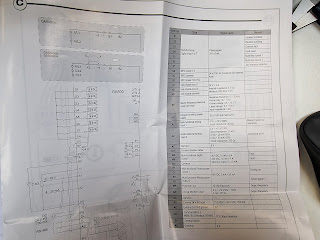
GA500 VFD control wiring:
I have 2 of these to wire up. The larger (4kW) version is for the spindle drive, with variable speed and braking resistor (and external EMC filter). The smaller (2.2kW) version is for the 1.5HP hydraulic pump and only runs at one set (forward) speed, without the need for a braking resistor. 

Apart from the analogue speed signal (0-10V), the control signals will be largely similar. Here's the larger one:


Acorn ethernet cable - COCKUP #1:
I knew it would be a mistake to get The Stupid Fat Bloke to mount the Acorn boards and expect them to connect up without a hitch. And sure enough, when I try to plug in the shielded ethernet cable that connects the Acorn to the PC, the relay board gets in the way. What an idiot - me for leaving it to him and him for being....The Stupid Fat Bloke.


Reasonable progress was happening until this point....


So, move the relay board down to clear the connector.


Getting there?
Yes but let's mount the display now. This is another Hanspree touch screen with Elived telescopic support arm. For now, I will simply mount the arm on the front of the machine. It will be some time before I've got swarf and coolant splashing about, so it's most conveniently mounted here for now. It's getting there:


And nipping round the back, you can just about make out the servo drivers. The signals and power are connected up, although fitting the covers on the Dsub connectors might be asking for trouble, so they will come later, once I've got things running.

So there we are. Arguably approaching 80-90% wired up. Some stuff not connected yet:

  • Hydraulic pump umbilical - not required yet. Will connect into the ETHER1616 board once the main system is sorted.
  • Limit and homing switches. I should connect these up before powering up the servos.
  • IEC socket for the monitor. I haven't decided how to mount the monitor or finish off the front panel, so no rush there.
  • Lube pump. Bit premature to power that thing up without anywhere to discharge the effluent. It simply wires up to the mains after the isolator switch, so no sweat.

Sunday, 8 May 2022

Bijur lube pump

The machine has the traditional Bijur-Delimon automatic lube pump for lubricating the slide ways. These are designed to deliver a fixed (but adjustable) squirt of way oil periodically, at a fixed interval which is determined by the gearing within the mechanism.


Mine's a C-2896, which is:
  • 120VAC
  • 1 pint(!) reservoir
  • 7.5 minute cycle time (at 50Hz) 
  • 0.2 - 1.0 ml per stroke, set by an adjustable collar. 

Usually these things are intended to be continuously powered while the machine is operating. Depending on the stroke, that would amount to between 8ml per hour and 1.6ml per hour. Sounds reasonable to me, so no need for a separate control to space out the events. However, I will enable it from the power circuit that runs the VFDs and servo drivers, so it's not simply pumping away when the PC is powered up with no actual movement happening.

120VAC power?
I will require a 120V transformer somewhere to power both this and the hydraulic solenoids used for the turret and tailstock. The total power draw will be miniscule, so it needn't take up much space.

Let's sanity check what the solenoids draw. I can't see it specified anywhere. The hydraulic solenoids are Sperry Vickers 414521 model and although it comes up in searches, there's no mention of power draw.

DC resistance measures as 27R, so clearly the inductance is the significant factor that determines the current draw. Rather than measure the current, let's estimate what it will be.

Out with the inductance meter. It rarely gets used but this is one occasion where it is actually helpful. 


130mH is an impedance of about 40R. In conjunction with 27R resistance, that would suggest a total impedance of around 50R. Clearly not - I guess the inductance increases significantly when the solenoid closes.

With a plug-in power meter and one of those 240-120V stepdown transformers, I'm seeing a static current in the transformer of 240mA (presumably that's all inductive) and a loaded current of 620mA. I can't be arsed to calculate the circuit values but the meter also reports 60W, which I assume is the real component that is responsible for the heating effect. That's a lot more than I'd expected, so I may need a few hundred VA worth of transformer in the end. 

A job for later, perhaps....

More electrical assembly - servo drivers

The work continues...

Wiring up the induction motors for the spindle and hydraulic pump into the VFDs. The phase connections are totally enclosed in flexible steel conduits - up until the last few inches. And as mentioned, the VFD supply sides both have EMC filters, so should be reasonably quiet, electrically speaking. Note also the red braking resistor for the spindle. There's no need for one on the hydraulic pump, obviously.


Now a mounting plate for the servo drivers. This mounts on the rear face of the headstock where it's away from any coolant and swarf. I've used nutserts both to provide threaded inserts to mount the drivers to the plate and also as through spacers to mount the plate to the headstock (M5 nutserts in the plate with M4 screws through to the headstock etc). Seems to work well.


Here are the 2 servo drivers temporarily mounted in place, with their EMC filter between them. Looks workable but lots of wiring still needed to connect it all up.


Spindle encoder connections

Thought you'd sorted the encoder?

Turns out that the Acorn spindle encoder input requires differential inputs, yet the 3 encoders that came with this machine are all single ended. Bollocks. Let's whip the spindle encoder off and take a look. It will have to come off anyway, most likely, so may as well dissect it and perhaps use it as an adaptor for its replacement. 


Yep, very similar to the ones that came on The Shiz - but single ended. It's very similar to the ones on the Shiz but different. No clue there. But the green is a chassis / screen connection, the red is +5V, black is 0V, so the yellow, orange and blue must be the A, B and Z. Clearly single ended.


This cast housing accommodates the bearings as well as the electronics.


The usual glass disk with graticules(?) and optical pickup (on the PCB). Shaft retained by tiny circlip.


Couldn't undo the tiny screw retaining the glass disk but removed the circlip and managed to drive the shaft and disk out easily enough.


Having driven out the mini bearings, there's a steel carrier that seems to be glued in place. That needs to come out but a tap with a hammer doesn't even touch it.


Butw e have the technology. 


I could simply turn down the extraneous gubbins but it's quicker to saw off the bulk of it...


...leaving just a fairly small job for the lathe.


Sorted. A bit of deburring and Bob's your aunty.


Time for a Chinesium clone. Try this one, which appears to have differential outputs, unlike the majority of the encoders out there. And a metric bored flexible coupling. Naturally the original shaft is 1/4" ie 6.35mm, so won't fit. I'll need to bore out one end to 1/4" so it fits the original driving shaft but we have the technology for that.


Arc Captain MIG200!

Yes indeed. Not content with a solitary TIG200PACDC TIG welder , I've gone for the matching pair. ie the MIG200 sister unit. There was ...