Before I get too carried away with the signal wiring, I have one critical subsystem to investigate. I'm planning to run the hydraulic pump from a 240V single phase VFD but that requires me to reconfigure it as a 240V (delta connected) machine. I'm pretty sure it's in 415V (star) at the moment.
Inevitably it's a bit of a mess down there, with oil and dust sticking to everything. On the other hand, this kind of muck usually responds well to WD40, a pot scrubber and loads of paper towels, so it shouldn't be too painful. Off we go...
First, take a note of the hose connections. It should be pretty obvious which hose goes where but you never know....
Remove 2 bolts and it just slides out.
6A / 240V 3-phase, 2HP 4-pole machine. This would run at 1500rpm no load in the UK at 50Hz, rather than 1800rpm in the US at 60Hz. No big deal but I may need to slightly tweak the VFD settings to give the same V/f ratio.
This label simply warns against sticking your fingers under this cover.
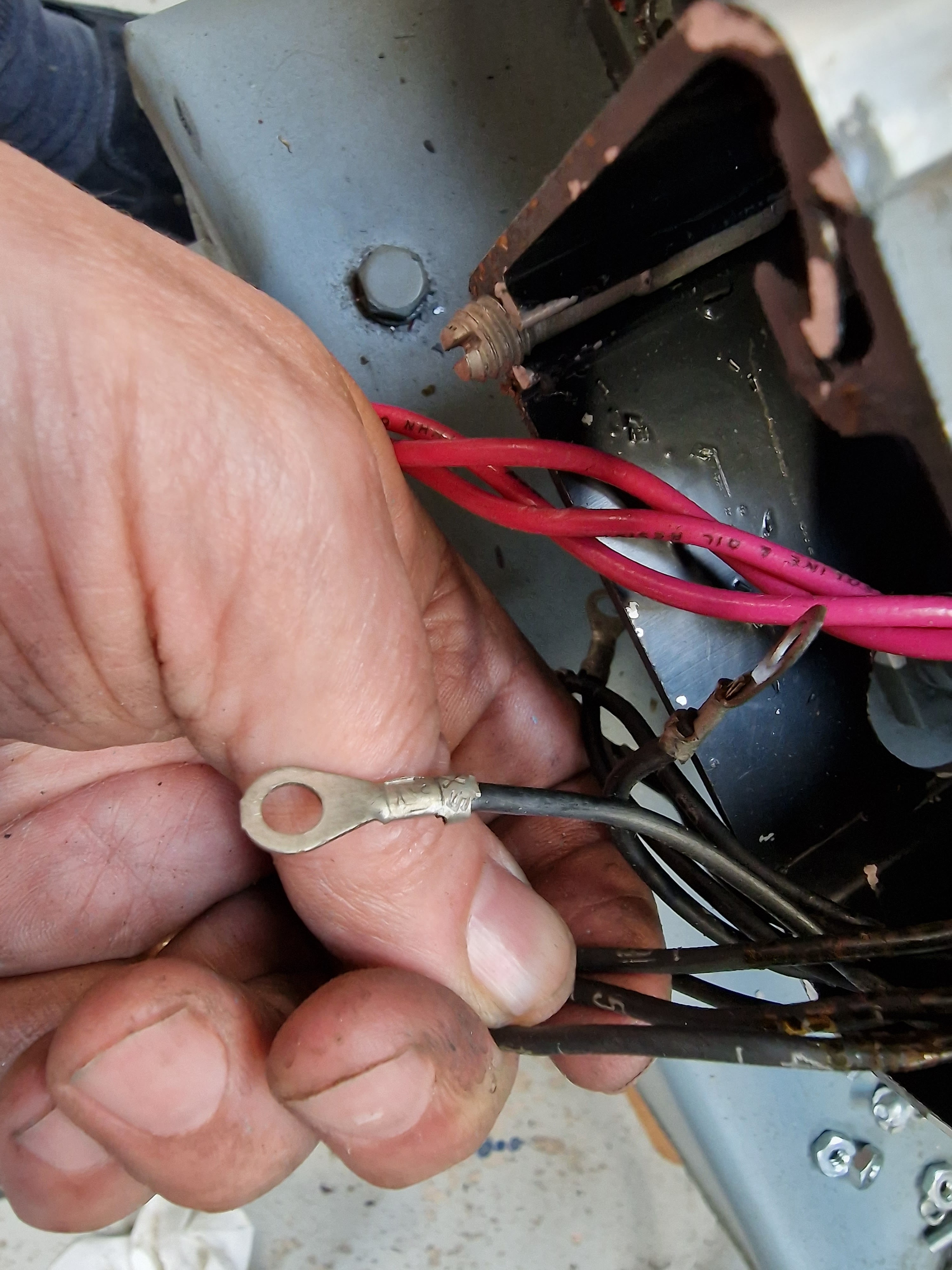
The motor windings aren't terminated in the usual terminal block. Instead, we have more of these nasty condom things concealing screw+nut connections.
Half an hour or so later, we have a cleaner pump assembly:
Yes, I still need to connect up the motor wires...
The tank is about 2/3 full and looks pretty clean. I can't be arsed to remove the whole lid to take a look at the bottom of the tanki. Imagine how that could go wrong!
The wires are all terminated with crimps and the wires are numbered, corresponding to the numbering on the name plate. I've just fitted blue M5 crimps on my red wires and reused the same screws.
The cavity doesn't clean up easily, as it's a rough cast finish with very little paint. However, it's a lot better now:
Looks all done to me now, notwithstanding the fact that I haven't actually powered it up. That will have to wait, as I don't yet have the blanking plugs for the manifold block and I don't want an oil bath in the workshop. If the motor is fucked, I will deal with it but for now at least I know it's fairly easy to pull it out to work on.
I've replaced the flexible steel conduit with a smaller one from one of the original servo motors.
Job done - let's shoo it back in!
There.
Now let's terminate the other end of the conduit next to its VFD and repeat the wiring exercise for the main spindle motor...


No comments:
Post a Comment