Friday 6 May 2022

Assembling the electrical controls - finally!

With most of the mechanicals reassembled, I can finally get on with assembling and connecting up all the electronics. I've not rushed into this so far, as it's helpful to get this right from the outset. The golden rule is normally to fit the electronics into an (apparently oversized) industrial cabinet and then fit it to the machine and connect it up. However, in this instance there's enough room in the machine enclosure to breed goats, so I'm reluctant to fit an additional layer of enclosure. Besides, the operator panel enclosure is pretty spacious, now that the CRT display and keyboard have been removed. Although I've sworn a few times not to try to cram stuff into too small a space, it's tempting to try to get the majority of the bits into that space. Will I regret this?

Firstly, let's see what we've got. 
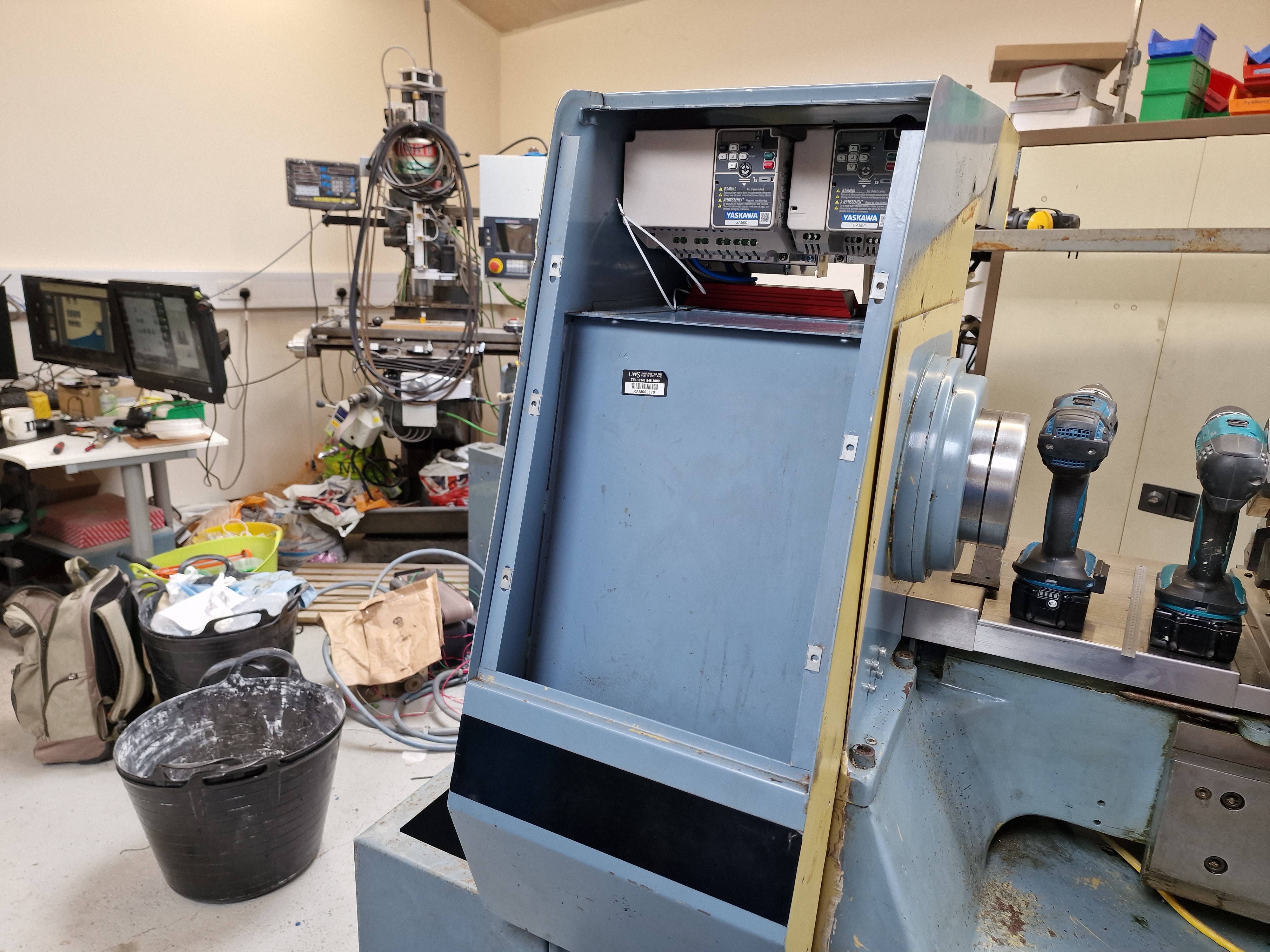
Yaskawa VFDs. 

They are the GA500 series, which are replacements for the old V1000 family. The one on the left is the 4kW model with external EMC filter (from Schaffner) and (red) braking resistor (sourced from RS). The smaller VFD is a 2.2kW model. These smaller versions come with the EMC filter built-in, which is an improvement over the V1000.


To enable the in-built EMC filter, you remove the screw from the "OFF" position and refit it into the "ON" position. Presumably this will enable EMC performance along the lines of Curve A (industrial) and certainly a lot better than your default, unfiltered HuanYang(?) Xmas cracker VFD.


Acorn system, ThinkCentre M700 PC and MeanWell PSU. 
I've installed the Centroid lathe software and got the system running now. Pretty quick and easy.


Enough talking!
After much buggerage, I've mounted the VFDs at the top of the operator enclosure. The top and rear of this space is actually relatively open, so it's not a heat trap despite appearances.


Mains isolator, power switch etc
I'm going to mount the isolator and power switch here, with the DIN rail mounted MCBs just above. That way, most of the mains wiring will be relatively confined and away from the control electronics.

Deburring the backs of the mounting holes was pretty tricky but I managed it by using a hand held Jacobs chuck. 


The second switch hasn't arrived yet but it's the same Siemens family as the main isolator, so I'm able to drill the holes etc.


Acorn system:
Here's my cunning plan for the Acorn baseplate. Piece of 2mm loominum sheet secured to the enclosure chassis.


From the rear you can see how I've spaced it off from the chassis and secured it at the top using 2 existing holes that were provided for the old Motorola VDU display thing.


Some time later, I've mounted the Acorn system in place.


The PSU supplied with the Acorn has 2 outputs, namely 5V and 24V but the Acorn no longer requires the 5V supply. Instead they have fitted a Recom encapsulated PSU to the Acorn board. This makes the (main 5V) output of the PSU redundant. On the other hand, the ETHER1616 expansion board requires 24V for the board and 5V for the ethernet switch. 

ETHER1616 expansion board:
Naturally, the ETHER1616 board comes with a single output (24V) PSU and a standalone wall wart PSU for the switch. 


WTF! So let's use the single (24V) output PSU for the Acorn (below) and use the 5V / 24V PSU for the ETHER1616 and switch. 

The ETHER1616  is an expansion board that provides an additional 16 channels of digital inputs and 16 relay outputs. I won't need anything like that amount of additional IO but the default 8 + 8 channels of the base Acorn are a bit limited for running a lathe with all the inputs such as the turret, tailstock, limit / home switches etc. So I will be mounting the ETHER1616 on its own plate, next to the VFDs.

I let The Stupid Fat Bloke loose on the task of making up a baseplate for this and he wasted no time (well 30 minutes actually) producing one with the wrong sized inserts. The holes in the Centroid boards are around 4mm diameter, so you can just about get an M4 screw through if the inserts are placed with deadly accuracy. But fitting M5 inserts isn't the path to happiness, so I had to take over the task from scratch and do the job properly.

I use cinch nuts to provide fixings in metalwork and when it comes to PCBAs, I simply turn them upside down ie use them as standoffs. Not quite how they are intended to be used but it works for me. Here we are, ready to fit the PCBAs.


Seems to fit the space.


And the PCBAs seem to fit the baseplate.


And finally, here's the PSU for the ETHER1616 and its ethernet switch (top left). I couldn't fit it on the baseplate without obscuring the terminal blocks and I'm not going to replace the open frame PSUs with DIN rail equivalents.


All done?
Apart from the missing power switch and a few DIN rail terminal blocks, the main task remaining now is to wire these various components together. That will take a few hours / days (/ weeks?)

No comments:

Post a Comment

Final assembly and test of the spindle nose adaptor - RESULT!!

After the recent distraction caused by the 3D scanner, resurrecting the 3D printer and buggering about with the throttle bodies for my Honda...