Sunday, 28 August 2022

Reassembling the Kitagawa chuck and machining the drawbar

Right, we are ready to start reassembling stuff again. 


The extension piece comes in handy for handling and testing out the assembly. Some of the clearances are actually pretty tight, so it's pretty tricky at times.


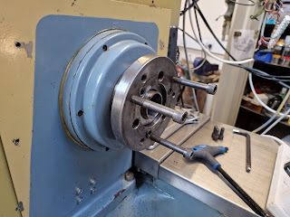
But the fixing holes holding the backplate to the spindle nose are too small for the bolts. Although it's a standard A2-5 spindle nose, the fixings themselves seem to differ between the Tree (probably imperial) and the backplate (likely metric). I'll need to open them up a little bit.


I'll simply locate each of the 6 holes individually with the probe and then enlarge each hole.


...with a carbide drill


With the backplate fitted, the runout is pretty bloody good. Less than 10um, both radial and axial, which is much better than the machine will achieve in terms of tolerance / accuracy. 


And with the chuck fitted, the runout is also pretty darned good too. That's encouraging. Or put it another way, I'd have been well pissed off if there had been any significant runout, having come this far.


This chuck is F heavy and very difficult to fit so let's be sensible and make up some form of lifting eye. I have a part set of soft jaws (only 2 in the set), so I can reuse one of those. I'll machine both of them, if only to help the vise to clamp them safely.

Squaring off:


Drilling


...and tapping. Starting with a machine tap in The Shiz...


...and finishing off with a tap wrench.


There.


Now I need something to weld a strap to. Something like this:


That's the bracket made up. Slotted the strap to fit the jaw so it can't rotate:


Next, weld a strap to the bracket.


Sorted.


Works well. That was worth the detour.


I need to use the fixing bolts to remove the backplate. Sounds shoddy but actually it doesn't take much to split them, so it's not as agricultural as it might sound. However, there's very little room to get a tool in there.


The drawbar certainly makes it through to the front. I suppose that's a good result in itself.


The next job is to machine the back end of the drawbar for the circlip that takes the thrust from the bearing. I'd like to get it in the correct axial position....


It's just about too long for the Bantam. But not quite. 


With the fixed steady and the toolpost flipped 180 degrees, I'm in with a chance.


There's a bit of an overhang and it's fairly thin wall tube, so I'll need to take small cuts.


Damned thing wants to walk out of the chuck but I don't want to distort it by overtightening the chuck. The solution was to grip it with emery paper.


It sang like a bird. The Blutack reduced the squealing a little bit. Good - that's the draw tube done.


The conical part is the mounting for the thrust bearing but it needs to be shortened about 15mm.


Getting there....


There.


Nice fit. FWIW, it's actually fitted backwards but this is just a trial fit.


Next - let's assemble the whole chuck / drawbar assembly for real and see what we've got...

Sunday, 14 August 2022

Testing and setting up the turret

Let's test the turret controls!

Well that worked. It required a bit of time for the air to be blown through the system, then I turned the pump speed up to 50hz. this pump is actually rated for 60hz being a US machine but it works fine at 50hz.

Here we are. 

And indeed it manages random tool changes. Phew.

Further mods to the PLC?

It feels very marginal in terms of mechanical margin / tolerances, so I can imagine that it may not be 100% dependable. However, there's still the "turret locked" switch input waiting to be connected up, so let's look at connecting it in.

Here's the relevant section of the RotateTurretStage2 stage:

;Reverse turret after timer expires in order to lock into correct tool location
; IF ToolTurretOffCurrentToolTimer THEN RST RotateToolTurret, SET ToolChangeComplete_M, RST ToolTurretEnable
; Change to:
IF ToolTurretOffCurrentToolTimer THEN RST RotateToolTurret, RST ToolTurretEnable
IF INP41 THEN SET ToolChangeComplete_M

If I have understood the original statement correctly, I have removed the RST ToolChangeComplete_M flag reset and changed it so it is conditional on the INP41 input being SET. Otherwise, if it is not, the toolchange won't be considered complete and the ATC timeout will result.

Let's modify the SRC file, compile it and try it out....

Saturday, 13 August 2022

Modifying the CNC12 PLC program to run a tool turret

With the servos, VFD etc all set up and working, it seemed like a good time to focus on cracking the controls for the turret toolchanger on the Tree. This is fairly simple - there's a single hydraulic solenoid that takes care of withdrawing the locking pawl, driving the turret off its locking "teeth" and rotating the turret (using a hydraulic motor). Once deactivated, the 2-way action of the solenoid applies reverse pressure, driving the turret backwards against the locking pawl, forcing the turret against its locking teeth and holding it there. There's also a Sanyo 8 way position switch (which appears to be a set of reed switches and a rotor-mounted magnet), which reports the current tool position.

There are several flavours of ATC catered for in the standard wizard options but none of them are exactly what I need. The closest uses 3 or 4 bit Gray code to report the position and a single output to drive the turret. Although I could arguably use a series of diodes to convert my 8-way switch outputs to Gray code, I'd rather do it in software. Otherwise it should be very close to what I require.

The PLC code is provided in the default cnct folder after installation and you are enabled / encouraged to make your own edits, then compile and test it for yourself.

Last night I made some changes to the PLC source code, as suggested by one of the Centroid staffers. This replaces the section that decodes the BCD inputs with a direct mapping of inputs from my ETHER1616 expansion board:
;==============================================================================
                               AtcGrayCode3Stage
;==============================================================================
IF TRUE THEN CurrentTurretPosition_W = 0
IF ToolTurretPosBit1 && ToolTurretPosBit2 && !ToolTurretPosBit3 THEN CurrentTurretPosition_W = 1
IF !ToolTurretPosBit1 && ToolTurretPosBit2 && !ToolTurretPosBit3 THEN CurrentTurretPosition_W = 2    ;**** Bit2
IF !ToolTurretPosBit1 && !ToolTurretPosBit2 && !ToolTurretPosBit3 THEN CurrentTurretPosition_W = 3
IF ToolTurretPosBit1 && !ToolTurretPosBit2 && !ToolTurretPosBit3 THEN CurrentTurretPosition_W = 4    ;**** Bit1
IF ToolTurretPosBit1 && !ToolTurretPosBit2 && ToolTurretPosBit3 THEN CurrentTurretPosition_W = 5
IF !ToolTurretPosBit1 && !ToolTurretPosBit2 && ToolTurretPosBit3 THEN CurrentTurretPosition_W = 6    ;**** Bit3
IF !ToolTurretPosBit1 && ToolTurretPosBit2 && ToolTurretPosBit3 THEN CurrentTurretPosition_W = 7
IF ToolTurretPosBit1 && ToolTurretPosBit2 && ToolTurretPosBit3 THEN CurrentTurretPosition_W = 8
IF TRUE THEN SV_PLC_CAROUSEL_POSITION = CurrentTurretPosition_W

With this (simpler) code:

;=========================================================================
                               ATCGrayCodeStage
;=========================================================================
; EME 2022-08-13 ATC control trials
; Input 1 on Ether1616 with A0 address = CNC12 input 33 etc
IF TRUE THEN CurrentTurretPosition_W = 0
IF INP33 THEN CurrentTurretPosition_W = 1
IF INP34 THEN CurrentTurretPosition_W = 2
IF INP35 THEN CurrentTurretPosition_W = 3
IF INP36 THEN CurrentTurretPosition_W = 4
IF INP37 THEN CurrentTurretPosition_W = 5
IF INP38 THEN CurrentTurretPosition_W = 6
IF INP39 THEN CurrentTurretPosition_W = 7
IF INP40 THEN CurrentTurretPosition_W = 8
IF TRUE THEN SV_PLC_CAROUSEL_POSITION = CurrentTurretPosition_W

Looks pretty straightforward. But obvs it wasn't clear to me if it was actually working when I tried it "dry" ie without the hydraulics running.

In the end, I went though the whole thing and deleted out everything that wasn't turret-related or specific to my turret type ("W4"). When I did that, it actually became quite understandable.

;=========================================================================
                             SetRequestedPositionStage
;=========================================================================
IF 1 == 1 THEN SET MEM1000
;=========================================================================
                             MonitorATCStage
;=========================================================================
;Stage is to Determine what ATC related stages should be enabled and disabled based
;on ATC type, Inputs selected, and ect.
;ATCType_W 0 = Manual Tool Changer
;ATCType_W 1 = Umbrella/Carousel
;ATCType_W 2 = Counter Turret
;ATCType_W 3 = Graycode 2 Output
;ATCType_W 4 = Graycode 1 Output - THIS IS THE CLOSEST TO MINE
;ATCType_W 5 = Time Based Turret
;ATCType_W 6 = Axis Based Turret
;ATCType_W 7 = Rack Based Tool Changer

;ATC Setup
IF (ATCType_W == 3) || (ATCType_W == 4) THEN RST ReportCarouselPositionStage,
SET ATCGrayCodeStage,
;Index the turret - IF THE VCP IS REQUESTING "Index TURRET"
IF SkinTurretIndex_M THEN SET TurretIndex_M, SET IndexTurretStage
; TurretIndex_M is a flag; IndexTurretStage IS A STAGE (CODE SECTION)

;Call out stage to perform tool change
IF M6 && (ATCType_W == 4) THEN SET RotateTurretStage2, RST TurretIndex_M

;=========================================================================
                               ATCGrayCodeStage
;=========================================================================
; EME 2022-08-13 ATC control trials
; Input 1 on Ether1616 with A0 address = CNC12 input 33 etc
IF TRUE THEN CurrentTurretPosition_W = 0
IF INP33 THEN CurrentTurretPosition_W = 1
IF INP34 THEN CurrentTurretPosition_W = 2
IF INP35 THEN CurrentTurretPosition_W = 3
IF INP36 THEN CurrentTurretPosition_W = 4
IF INP37 THEN CurrentTurretPosition_W = 5
IF INP38 THEN CurrentTurretPosition_W = 6
IF INP39 THEN CurrentTurretPosition_W = 7
IF INP40 THEN CurrentTurretPosition_W = 8
IF TRUE THEN SV_PLC_CAROUSEL_POSITION = CurrentTurretPosition_W

;=========================================================================
                                IndexTurretStage
;=========================================================================
IF TurretIndex_M && (CurrentTurretPosition_W == SV_MACHINE_PARAMETER_161) 
THEN RequestedTurretPosition_W = 1
; SV_MACHINE_PARAMETER_161 SHOWS THE MAX TOOL NUMBER
; IF CURRENTLY AT MAX TOOL NUMBER, THE NEXT TOOL POSITION IS #1
IF TurretIndex_M && (CurrentTurretPosition_W != SV_MACHINE_PARAMETER_161) 
THEN RequestedTurretPosition_W = CurrentTurretPosition_W +1
IF (ATCType_W == 2) || (ATCType_W == 4) THEN SET RotateTurretStage2, RST IndexTurretStage
; THE CORRECT STAGE FOR INCREMENTING TYPE 4 is RotateTurretStage2

;=========================================================================
                                HomeTurretStage
;=========================================================================
;If not at home, turn turret on
IF M18 && !TurretHomed_M THEN SET RotateToolTurret
; THIS IS ONLY REQUIRED IF CUSTOM HOMING MACRO M18 IS CALLED
;Turn timer on once home signal is triggered
IF M18 && ToolTurretSyncBit THEN SET ToolTurretOffCurrentToolTimer

;Turn motor off and assign value of 1 when timer is up
IF ToolTurretOffCurrentToolTimer THEN RST RotateToolTurret, CurrentTurretPosition_W = 1, SET TurretHomed_M

;=========================================================================
                                RotateTurretStage2
;=========================================================================
;--1 Output GrayCode Turret
;Determine the desired tool location
IF !TurretIndex_M THEN RequestedTurretPosition_W = SV_TOOL_NUMBER

;Error if Tool # is Invalid
IF RequestedTurretPosition_W > SV_MACHINE_PARAMETER_161
THEN FaultMsg_W = INVALID_TOOL_REQUEST, SET OtherFault_M

;If not at desired location start rotating the turret
IF (M6 || TurretIndex_M) && (RequestedTurretPosition_W != CurrentTurretPosition_W) 
THEN SET RotateToolTurret, SET ToolChangeTimeOutTimer, SET ToolTurretEnable

;Turn the timer on once at the desired location to go slightly past the tool location
;in order to reverse into correct tool location
IF (M6 || TurretIndex_M) && (RequestedTurretPosition_W == CurrentTurretPosition_W) 
THEN SET ToolTurretOffCurrentToolTimer 
; This is the overshoot time, to enable the turret to go slightly past the final position. 
; Uses timer T21 / Parameter #851 - default 0.75s

;Reverse turret after timer expires in order to lock into correct tool location
IF ToolTurretOffCurrentToolTimer THEN RST RotateToolTurret, SET ToolChangeComplete_M, RST ToolTurretEnable
; Uses timer T22 / Parameter #849 - default 10s

;If timer expires set fault
IF ToolChangeTimeOutTimer THEN SET SV_STOP, FaultMsg_W = TURRET_TIMEOUT_FAULT


;=========================================================================
                        MonitorIndexATCRequestStage
;=========================================================================
; I'VE NO IDEA IF THIS IS REQUIRED> LOOKS LIKE CAROUSEL / RACK ATC TO ME
IF SkinATCIndexMinus_M THEN (ATCIndexMinusPD)
IF (ATCIndexMinusPD && !DoingIndex_M) && (!SV_PROGRAM_RUNNING ||(SV_MDI_MODE && 
  SV_PROGRAM_RUNNING && !DoingM6_M)) 
  THEN SET DoingIndexMinus_M, SET DoingIndex_M, SET RequestedBinPositionStage  

IF SkinATCIndexPlus_M THEN (ATCIndexPlusPD)  
IF (ATCIndexPlusPD && !DoingIndex_M) && (!SV_PROGRAM_RUNNING ||(SV_MDI_MODE && 
  SV_PROGRAM_RUNNING && !DoingM6_M)) 
  THEN SET DoingIndexPlus_M, SET DoingIndex_M, SET RequestedBinPositionStage

IF (ATCIndexMinusPD || ATCIndexPlusPD) && M6
  THEN InfoMsg_W = MANUAL_INDEX_WHILE_ATC_MSG, RST DoingIndex_M   

IF M6 && !DoingIndex_M 
  THEN (M6PD)
; M6 is toolchange
  
IF M6 && (DoingIndexMinus_M || DoingIndexPlus_M)
  THEN RST M6, InfoMsg_W = ATC_WHILE_MANUAL_INDEX_MSG 
  
IF M6PD THEN SET DoingM6_M, SET RequestedBinPositionStage

;=========================================================================
                                TailStockStage
;=========================================================================
; MIGHT AS WELL LEAVE THIS IN, AS I'LL BE LOOKING AT THIS SOON
IF SkinTailStock_M THEN (TailStockPD)
IF (TailStockPD && !SV_PROGRAM_RUNNING && !TailStockInOut) || (M32 && SV_PROGRAM_RUNNING)
THEN SET TailStockInOut, SET Aux11LED
IF (TailStockPD && !SV_PROGRAM_RUNNING && TailStockInOut) || (!M32 && SV_PROGRAM_RUNNING)
THEN RST TailStockInOut, RST Aux11LED

;IF TailOut_T THEN RST M33, RST TailOut_T ;Reset After 15 Seconds
; M32 = tailstock in custom macro
; M33 = tailstock out custom macro

It all looks pretty reasonable with the exception of the MonitorIndexATCRequestStage bit, which I suspect isn't relevant here.

And indeed, that all seems to work. Admittedly, I haven't got the hydraulic pump running but everything else computes. If you run the PLC Detective (press Alt-E while CNC12 is running), you can see the status of the variables that are displayed as they change. So hovering the mouse over RequestedTurretPosition_W would show the currently requested tool position etc. That's pretty handy for checking what it thinks is going on.

Saturday, 6 August 2022

Modelling up the Kitagawa chuck and the spindle - and threading the connector

Que? Why would you do that?

Indeed - why would you? Well the original drawbar has an imperial (2"-20tpi) female thread at the chuck end that is designed to pull on the collets, while the Kitagawa chuck has a metric (50mm x 1.5mm) female thread. And there's a fairly large gap between the 2 items. As I seem to have committed to being able to use the Kitagawa chuck, I need to figure out how to connect them. This decision to use the Kitagawa doesn't rule out using the D1-3 chucks but it's my first line of attack, rightly or wrongly.

The front of the spindle nose has a clearance bore for 2" / 50.8mm, although the rear of the spindle (past the first 100mm or so) has a larger bore of ~53mm. I need to be able to insert this connector piece from the front of the spindle, so my max diameter should be the 50.5mm dimension.

It's pretty busy in there, where the chuck, adaptor plate and spindle nose come together. Will there be a clash? How long does the connector need to be? What diameter should it be?

Over an idle weekend, my first after 2 weeks with a chest infection and 2 weeks break in Scotland, I modelled up the chuck, adaptor plate and spindle nose assembly. This was pretty complex but as there's nothing available for download on the Kitagawa site, it didn't look as if there was much choice between this and simply making the bits up by hand as I went, using trial and error. This is pretty close to reality and a great start when it comes to figuring out what the adaptor piece needs to look like and where there may be clashes.


The moving "master jaw" was quite a thing to model up and worthy of a "Fusion 360 challenge" in anyone's books. Not that the main chuck body or the other compts were a great deal easier.


And a connector?
...and yes, here's the connector piece. Very simple really. A piece of 2" thick wall tube with a 2" x 20tpi thread at one end (for the drawbar) and a 50mm x 1.5mm thread at the other. The through bore of the spindle nose is 50.8mm at its narrowest, so I need to use 2" stock as the starter. I need perhaps 3mm or so wall thickness to allow for a half decent thread depth and some residual material. Going much thicker will simply lose me some of my through bore. 


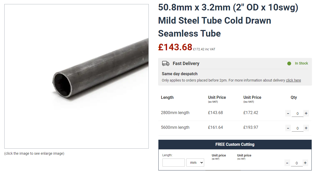
There seems to be a reasonably common size of 3.25mm (slightly over 1/8") and I want CDS (cold drawn steel) to get reasonably good dimensional control. Quite a few places stock the stuff but most are geared up to sell 3m lengths and charge through the nose for cutting shorter lengths.

metals4u.co.uk seem to sell the stuff although since ordering on Monday, the price seems to have increased from £40, as paid....

... to £143 - plus carriage and vat. Whaaaat?
Go figure. But I have it here now. Let's get threading.....

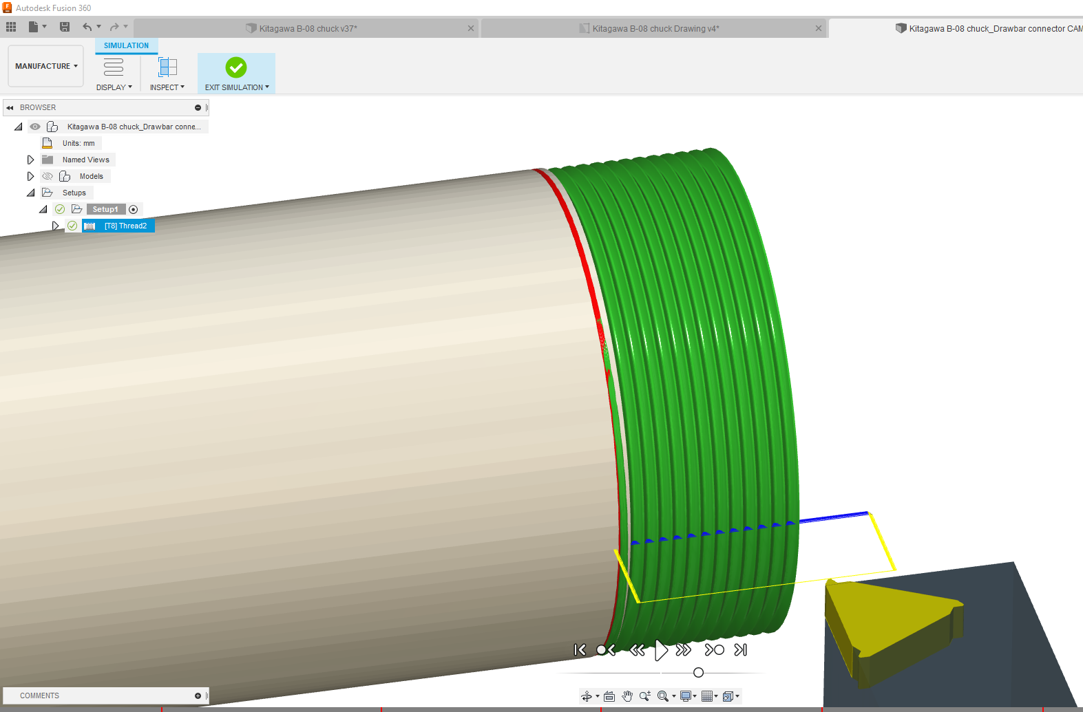
CAM toolpaths:

Simulates like this:


With the default G33 cycle, this is the output:
%
(3330)
N10 G7
N11 G18
N12 G90
N13 G21
N14 G53 G0 X100.

(2 - 20 THREAD)
N15 M0 (CHANGE TO T8 ON REAR TOOL POST)
N16 T8 M6 G43
N18 G54
N19 M8
N20 G97 S500 M3
N21 G95
N22 G90 G0 X70.8 Z2.
N23 G0 Z6.708
N24 X49.991
N25 G33 Z-19.068 K1.27
N26 X50.698 Z-19.422 K1.796
N27 G0 X54.698
N28 Z6.627
N29 X49.698
N30 G33 Z-19.003 K1.27
N31 X50.698 Z-19.503 K1.796
N32 G0 X54.698
N33 Z6.565
N34 X49.474
N35 G33 Z-18.953 K1.27
N36 X50.698 Z-19.565 K1.796
N37 G0 X54.698
N38 Z6.512
N39 X49.284
N40 G33 Z-18.91 K1.27
N41 X50.698 Z-19.618 K1.796
N42 G0 X54.698
N43 Z6.466
N44 X49.117
N45 G33 Z-18.873 K1.27
N46 X50.698 Z-19.664 K1.796
N47 G0 X54.698
N48 Z6.424
N49 X48.966
N50 G33 Z-18.84 K1.27
N51 X50.698 Z-19.706 K1.796
N52 G0 X54.698
N53 Z6.386
N54 X48.828
N55 G33 Z-18.809 K1.27
N56 X50.698 Z-19.744 K1.796
N57 G0 X54.698
N58 Z6.35
N59 X48.698
N60 G33 Z-18.78 K1.27
N61 X50.698 Z-19.78 K1.796
N62 G0 X54.698
N63 Z6.35
N64 X48.698
N65 G33 Z-18.78 K1.27
N66 X50.698 Z-19.78 K1.796
N67 G0 X70.8
N68 Z2.

N69 M9
N70 M5
N71 G53 G0 X100.
N72 M30
%

Whereas with the tapping cycle G76 selected in the threading operation "passes" tab (and the post options), I get a slightly neater output: 

%
(1001)
N10 G7
N11 G18
N12 G90
N13 G21
N14 G53 G0 X100.

(2 - 20 THREAD)
N15 M0 (CHANGE TO T8 ON REAR TOOL POST)
N16 T8 M6 G43
N18 G54
N19 M8
N20 G97 S500 M3
N21 G95
N22 G90 G0 X70.8 Z2.
N23 G0 Z6.708
N24 X54.698
N25 G76 P1.27 Z-19.78 I-4. J0.25 K2. R2. Q29. H1. E1. L0
N26 G0 X70.8 Z6.708
N27 Z-19.78
N28 Z2.

N29 M9
N30 M5
N31 G53 G0 X100.
N32 M30
%

I think I'll go with this one.

I've got some 60 degree 1.5mm threading inserts which must be pretty close for this thread. Perhaps a slightly bigger nose radius but I'll use the same 1.5mm insert for both threads, rather than change to a 1.25mm insert, just to be lazy.

But first I need to set up a Tool 8 in the LinuxCNC tool library, otherwise it will get pissed off when I try to run the program.

Let's get cutting:
Let's cut off some lengths of tube ready for action. Given that I have 3m of the stuff to play with, I'll cut off 3 lengths of the required 135mm. Then I can play about and make a few mistakes, sorry should have said "trials".


Hmm. This stuff looks more like electric resistance welded (REW) than cold drawn steel (CDS), which may explain why it was somewhat cheaper. I'm guessing this may make threading a little trickier than I'd like. Ho hum. 

Sure enough, it's as crooked as a tramp's dick, with something like 0.25mm total runout. Well, let's see how it goes.


Rather than mess about with 4 jaws and tailstocks, I'll see if I can get away with the 3 jaw and light-ish cuts.

Swarf time!
On the first attempt, I touched off and then told LinuxCNC that this was 50.8mm diameter. Pretty dumb move, as the runout was enough to be visible. Consequently, the finished thread was a sloppier fit that I was happy with. Normally you'd take a skim cut, measure it and then set the diameter accordingly. However, the nominal thread diameter is the same as the alleged tube diameter here, so that wasn't an option.

Useful to have had a practice run, so next time I completed the threading after telling LinuxCNC the touchoff diameter was 50.0mm, then repeating the threading operating after increasing the diameter 0.2mm or so at a time. Once this was done and I had a decent fit, I was able to thread the third item in one operation. As you can see, I got the thread pretty much spot on. Once I cleaned the drawbar thread and added some oil, it fitted a treat - and stopped squealing.


Then there were three:


This left the metric end to be threaded M50 x 1.5mm. I started out using the first sample, as it was already scrap at the imperial end. 

First, turn the end down to 50mm for the first 32mm or so:


Just as well I started out with the scrap piece, as I accidentally accepted the Fusion 360 default threading option of constant stepdown per pass with zero feed in angle. So at each pass, the tool load increased significantly until after only a few passes the workpiece slipped in the chuck and I had a mini crash on my hands. Ooof.


The tube itself was mightily fucked but the threading insert wasn't remotely bothered.


Move onto the second workpiece, using the correct(!) toolpath settings and after one pass, I was bang on the money.


So I have one completely scrap attempt and one perfect. I'm leaving the third piece with just one end threaded (2" x 20tpi) in case I need to change the length of the connector later.


Metric end:


Imperial end:


Fucked end. Amazing the insert didn't even complain:


Crushed end:


Bottom line, it fits the chuck drawnut nicely...


..and the drawbar too.


We'll call that a win. Not a bad result after almost 5 weeks away from the machines.

TIG welder up and running - after some fault diagnostics and repair

Finally got some time to connect up the flow meter and argon hose. Plugged in the torch and ground cables and the torch hose etc. Powered it...