Que? Why would you do that?
Indeed - why would you? Well the original drawbar has an imperial (2"-20tpi) female thread at the chuck end that is designed to pull on the collets, while the Kitagawa chuck has a metric (50mm x 1.5mm) female thread. And there's a fairly large gap between the 2 items. As I seem to have committed to being able to use the Kitagawa chuck, I need to figure out how to connect them. This decision to use the Kitagawa doesn't rule out using the D1-3 chucks but it's my first line of attack, rightly or wrongly.
The front of the spindle nose has a clearance bore for 2" / 50.8mm, although the rear of the spindle (past the first 100mm or so) has a larger bore of ~53mm. I need to be able to insert this connector piece from the front of the spindle, so my max diameter should be the 50.5mm dimension.
It's pretty busy in there, where the chuck, adaptor plate and spindle nose come together. Will there be a clash? How long does the connector need to be? What diameter should it be?
Over an idle weekend, my first after 2 weeks with a chest infection and 2 weeks break in Scotland, I modelled up the chuck, adaptor plate and spindle nose assembly. This was pretty complex but as there's nothing available for download on the Kitagawa site, it didn't look as if there was much choice between this and simply making the bits up by hand as I went, using trial and error. This is pretty close to reality and a great start when it comes to figuring out what the adaptor piece needs to look like and where there may be clashes.

The moving "master jaw" was quite a thing to model up and worthy of a "Fusion 360 challenge" in anyone's books. Not that the main chuck body or the other compts were a great deal easier.


And a connector?
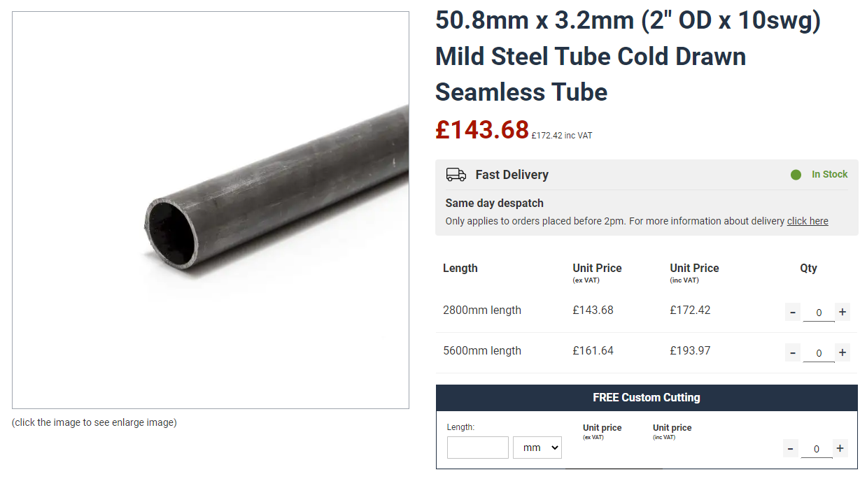
...and yes, here's the connector piece. Very simple really. A piece of 2" thick wall tube with a 2" x 20tpi thread at one end (for the drawbar) and a 50mm x 1.5mm thread at the other. The through bore of the spindle nose is 50.8mm at its narrowest, so I need to use 2" stock as the starter. I need perhaps 3mm or so wall thickness to allow for a half decent thread depth and some residual material. Going much thicker will simply lose me some of my through bore.

There seems to be a reasonably common size of 3.25mm (slightly over 1/8") and I want CDS (cold drawn steel) to get reasonably good dimensional control. Quite a few places stock the stuff but most are geared up to sell 3m lengths and charge through the nose for cutting shorter lengths.
metals4u.co.uk seem to sell the stuff although since ordering on Monday, the price seems to have increased from £40, as paid....

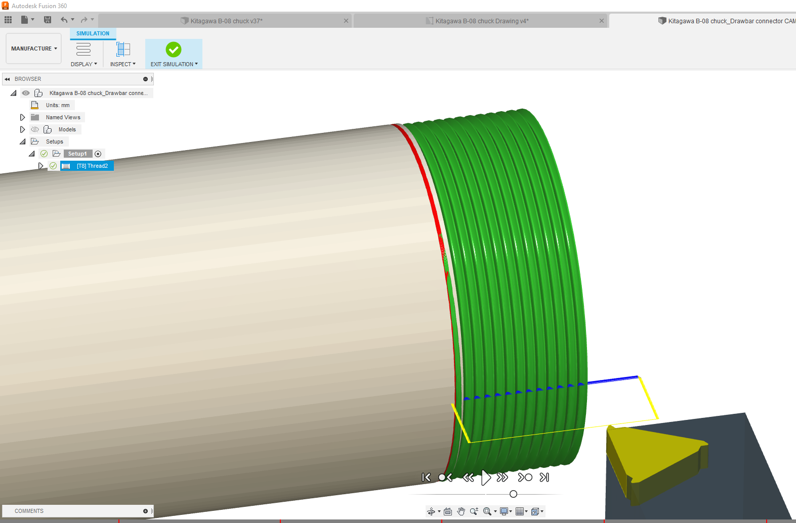
CAM toolpaths:

Simulates like this:
With the default G33 cycle, this is the output:
%
(3330)
N10 G7
N11 G18
N12 G90
N13 G21
N14 G53 G0 X100.
(2 - 20 THREAD)
N15 M0 (CHANGE TO T8 ON REAR TOOL POST)
N16 T8 M6 G43
N18 G54
N19 M8
N20 G97 S500 M3
N21 G95
N22 G90 G0 X70.8 Z2.
N23 G0 Z6.708
N24 X49.991
N25 G33 Z-19.068 K1.27
N26 X50.698 Z-19.422 K1.796
N27 G0 X54.698
N28 Z6.627
N29 X49.698
N30 G33 Z-19.003 K1.27
N31 X50.698 Z-19.503 K1.796
N32 G0 X54.698
N33 Z6.565
N34 X49.474
N35 G33 Z-18.953 K1.27
N36 X50.698 Z-19.565 K1.796
N37 G0 X54.698
N38 Z6.512
N39 X49.284
N40 G33 Z-18.91 K1.27
N41 X50.698 Z-19.618 K1.796
N42 G0 X54.698
N43 Z6.466
N44 X49.117
N45 G33 Z-18.873 K1.27
N46 X50.698 Z-19.664 K1.796
N47 G0 X54.698
N48 Z6.424
N49 X48.966
N50 G33 Z-18.84 K1.27
N51 X50.698 Z-19.706 K1.796
N52 G0 X54.698
N53 Z6.386
N54 X48.828
N55 G33 Z-18.809 K1.27
N56 X50.698 Z-19.744 K1.796
N57 G0 X54.698
N58 Z6.35
N59 X48.698
N60 G33 Z-18.78 K1.27
N61 X50.698 Z-19.78 K1.796
N62 G0 X54.698
N63 Z6.35
N64 X48.698
N65 G33 Z-18.78 K1.27
N66 X50.698 Z-19.78 K1.796
N67 G0 X70.8
N68 Z2.
N69 M9
N70 M5
N71 G53 G0 X100.
N72 M30
%
Whereas with the tapping cycle G76 selected in the threading operation "passes" tab (and the post options), I get a slightly neater output:
%
(1001)
N10 G7
N11 G18
N12 G90
N13 G21
N14 G53 G0 X100.
(2 - 20 THREAD)
N15 M0 (CHANGE TO T8 ON REAR TOOL POST)
N16 T8 M6 G43
N18 G54
N19 M8
N20 G97 S500 M3
N21 G95
N22 G90 G0 X70.8 Z2.
N23 G0 Z6.708
N24 X54.698
N25 G76 P1.27 Z-19.78 I-4. J0.25 K2. R2. Q29. H1. E1. L0
N26 G0 X70.8 Z6.708
N27 Z-19.78
N28 Z2.
N29 M9
N30 M5
N31 G53 G0 X100.
N32 M30
%
I think I'll go with this one.
I've got some 60 degree 1.5mm threading inserts which must be pretty close for this thread. Perhaps a slightly bigger nose radius but I'll use the same 1.5mm insert for both threads, rather than change to a 1.25mm insert, just to be lazy.
But first I need to set up a Tool 8 in the LinuxCNC tool library, otherwise it will get pissed off when I try to run the program.
Let's get cutting:
Let's cut off some lengths of tube ready for action. Given that I have 3m of the stuff to play with, I'll cut off 3 lengths of the required 135mm. Then I can play about and make a few mistakes, sorry should have said "trials".

Hmm. This stuff looks more like electric resistance welded (REW) than cold drawn steel (CDS), which may explain why it was somewhat cheaper. I'm guessing this may make threading a little trickier than I'd like. Ho hum.
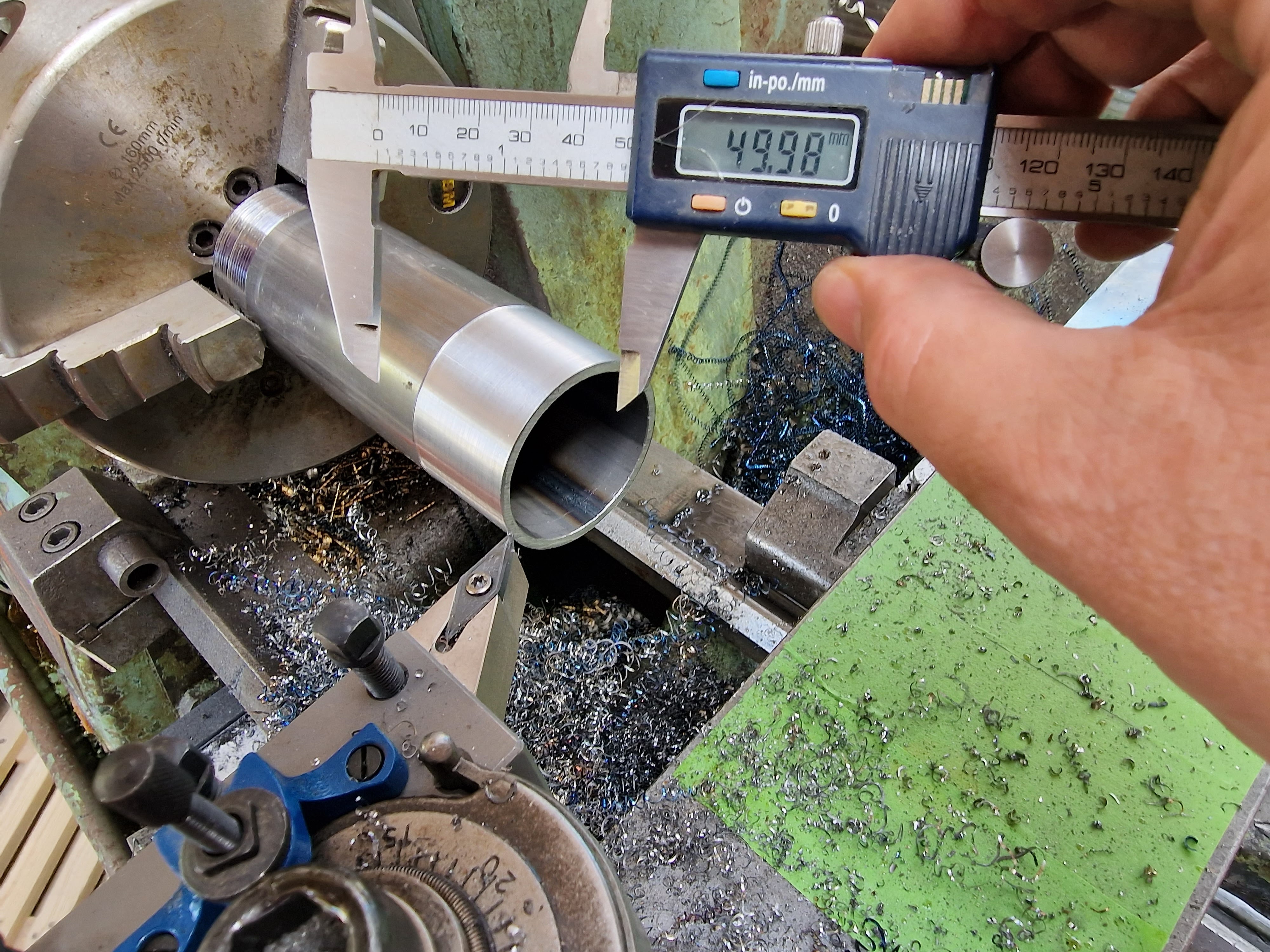
Sure enough, it's as crooked as a tramp's dick, with something like 0.25mm total runout. Well, let's see how it goes.

Rather than mess about with 4 jaws and tailstocks, I'll see if I can get away with the 3 jaw and light-ish cuts.
Swarf time!
On the first attempt, I touched off and then told LinuxCNC that this was 50.8mm diameter. Pretty dumb move, as the runout was enough to be visible. Consequently, the finished thread was a sloppier fit that I was happy with. Normally you'd take a skim cut, measure it and then set the diameter accordingly. However, the nominal thread diameter is the same as the alleged tube diameter here, so that wasn't an option.
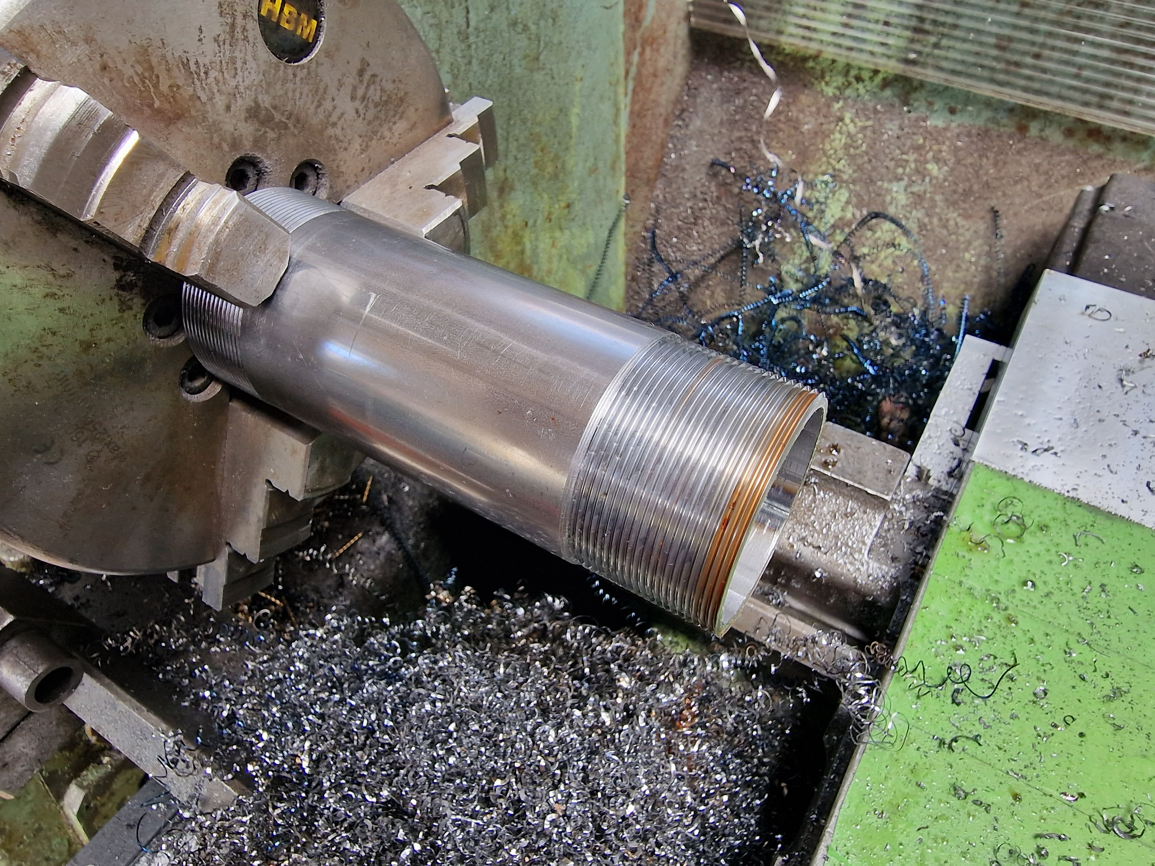
Useful to have had a practice run, so next time I completed the threading after telling LinuxCNC the touchoff diameter was 50.0mm, then repeating the threading operating after increasing the diameter 0.2mm or so at a time. Once this was done and I had a decent fit, I was able to thread the third item in one operation. As you can see, I got the thread pretty much spot on. Once I cleaned the drawbar thread and added some oil, it fitted a treat - and stopped squealing.


Then there were three:

This left the metric end to be threaded M50 x 1.5mm. I started out using the first sample, as it was already scrap at the imperial end.
First, turn the end down to 50mm for the first 32mm or so:
Just as well I started out with the scrap piece, as I accidentally accepted the Fusion 360 default threading option of constant stepdown per pass with zero feed in angle. So at each pass, the tool load increased significantly until after only a few passes the workpiece slipped in the chuck and I had a mini crash on my hands. Ooof.

The tube itself was mightily fucked but the threading insert wasn't remotely bothered.

Move onto the second workpiece, using the correct(!) toolpath settings and after one pass, I was bang on the money.

So I have one completely scrap attempt and one perfect. I'm leaving the third piece with just one end threaded (2" x 20tpi) in case I need to change the length of the connector later.

Metric end:

Imperial end:

Fucked end. Amazing the insert didn't even complain:
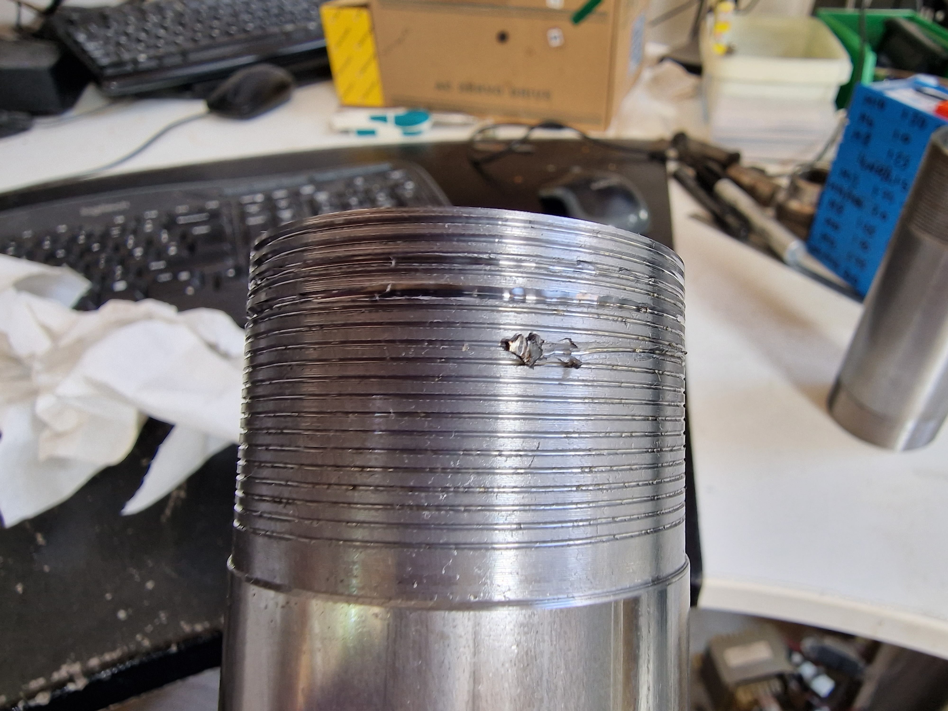
Crushed end:

Bottom line, it fits the chuck drawnut nicely...


..and the drawbar too.


No comments:
Post a Comment