Right, we are ready to start reassembling stuff again.
The extension piece comes in handy for handling and testing out the assembly. Some of the clearances are actually pretty tight, so it's pretty tricky at times.

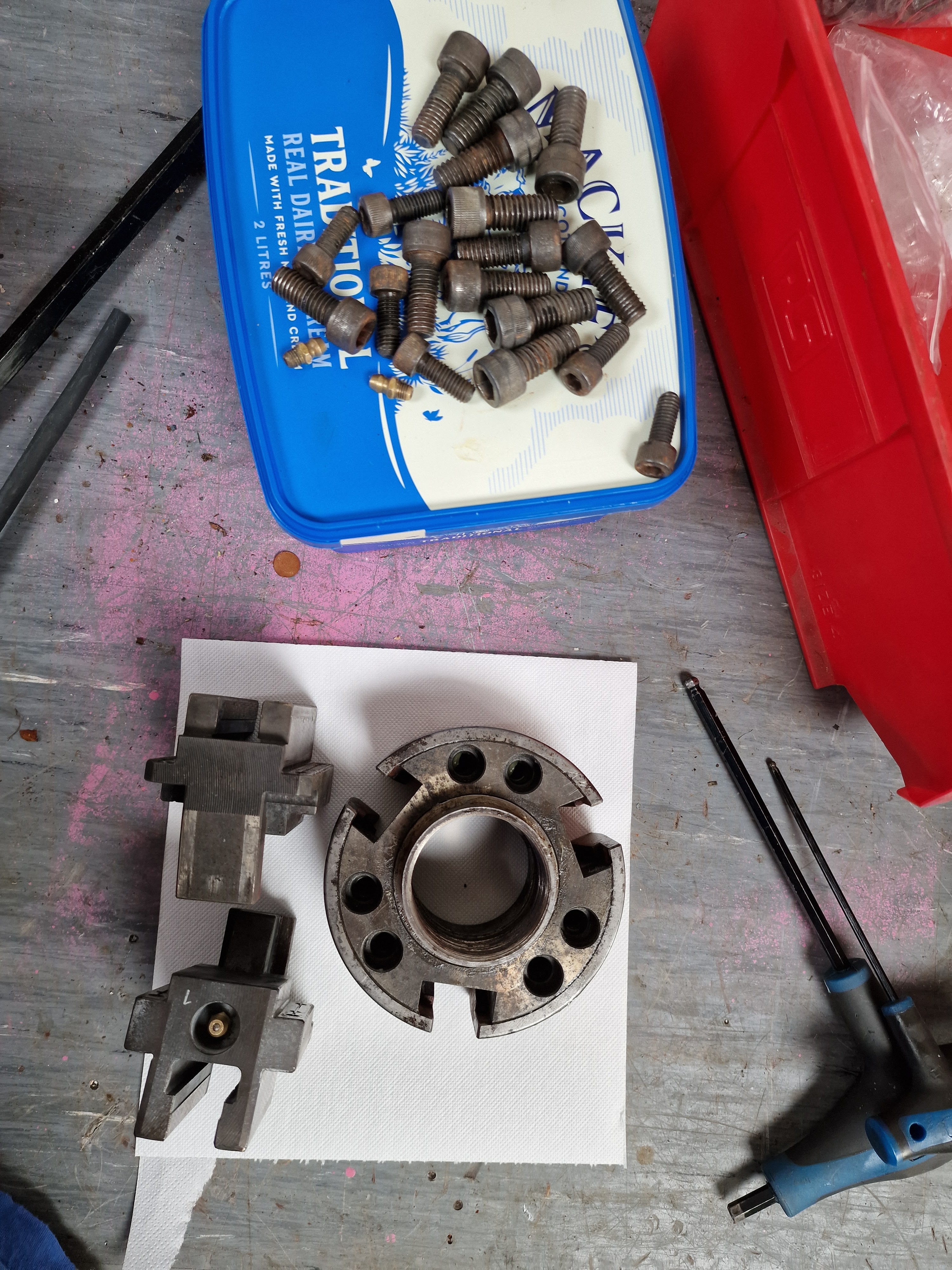
But the fixing holes holding the backplate to the spindle nose are too small for the bolts. Although it's a standard A2-5 spindle nose, the fixings themselves seem to differ between the Tree (probably imperial) and the backplate (likely metric). I'll need to open them up a little bit.

I'll simply locate each of the 6 holes individually with the probe and then enlarge each hole.


With the backplate fitted, the runout is pretty bloody good. Less than 10um, both radial and axial, which is much better than the machine will achieve in terms of tolerance / accuracy.


And with the chuck fitted, the runout is also pretty darned good too. That's encouraging. Or put it another way, I'd have been well pissed off if there had been any significant runout, having come this far.

This chuck is F heavy and very difficult to fit so let's be sensible and make up some form of lifting eye. I have a part set of soft jaws (only 2 in the set), so I can reuse one of those. I'll machine both of them, if only to help the vise to clamp them safely.
Squaring off:

Drilling


...and tapping. Starting with a machine tap in The Shiz...

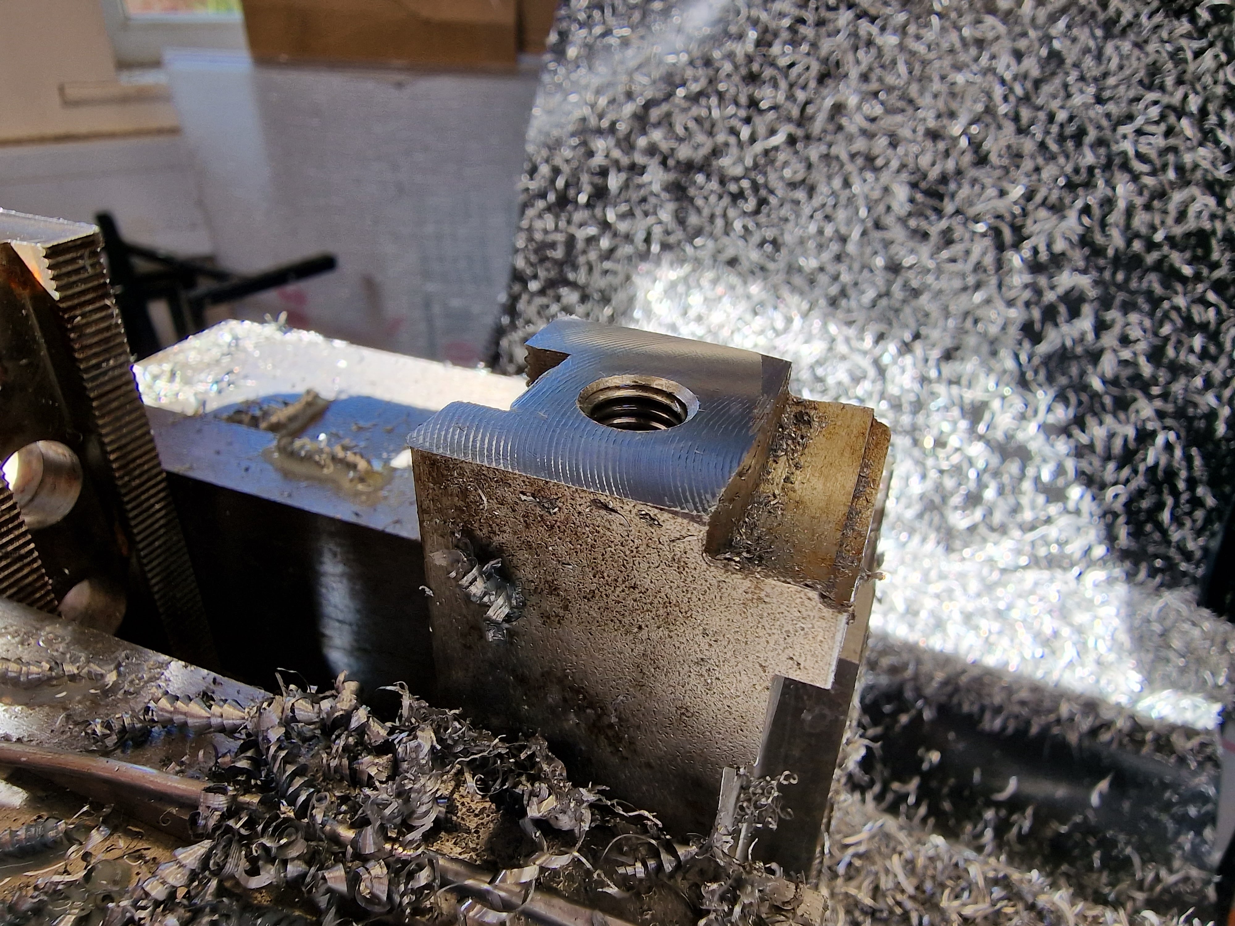
...and finishing off with a tap wrench.

There.

Now I need something to weld a strap to. Something like this:


That's the bracket made up. Slotted the strap to fit the jaw so it can't rotate:

Next, weld a strap to the bracket.

Sorted.

Works well. That was worth the detour.

I need to use the fixing bolts to remove the backplate. Sounds shoddy but actually it doesn't take much to split them, so it's not as agricultural as it might sound. However, there's very little room to get a tool in there.

The drawbar certainly makes it through to the front. I suppose that's a good result in itself.

The next job is to machine the back end of the drawbar for the circlip that takes the thrust from the bearing. I'd like to get it in the correct axial position....


It's just about too long for the Bantam. But not quite.

With the fixed steady and the toolpost flipped 180 degrees, I'm in with a chance.

There's a bit of an overhang and it's fairly thin wall tube, so I'll need to take small cuts.

Damned thing wants to walk out of the chuck but I don't want to distort it by overtightening the chuck. The solution was to grip it with emery paper.

It sang like a bird. The Blutack reduced the squealing a little bit. Good - that's the draw tube done.

The conical part is the mounting for the thrust bearing but it needs to be shortened about 15mm.


Getting there....
There.


Nice fit. FWIW, it's actually fitted backwards but this is just a trial fit.

Next - let's assemble the whole chuck / drawbar assembly for real and see what we've got...


No comments:
Post a Comment