Monday, 21 February 2022

Teardown time!

Let's carry on from where I left off last weekend. 

Z axis drive:
Last time, I removed the end cover from the Z axis ballscrew drive. For one thing I need to access the motor so I can figure out whether or not to retain it or replace it with something more modern. It's certainly a DC brushed motor, so would require a DC servo (eg the cncdrive DG4S16035) but I'd like to see a model and manufacturer and ideally be able to find a datasheet for it, as well as assess the state of the brushes etc. All I know is that it had a 100Vdc supply (70Vac before rectification).


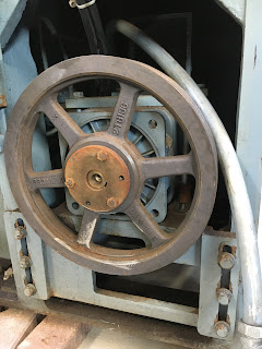
The flex drive for the encoder was a bit fiddly to remove but having done so, I can now see the belt drive and the servo motor mounting. The latter is a fairly simple plate with slotted holes for belt tensioning.


Although I managed to remove the mounting bolts, the motor is too big (tight fit) to remove without removing the plate.


Ooof


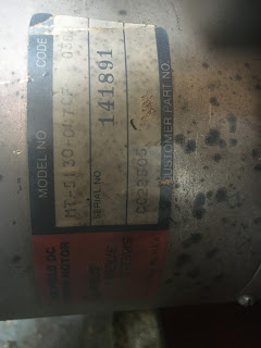
Finally, a motor plate. EG&G are long gone. The model number seems to be MT-5130-047CF. No actual ratings are given anywhere on the motor. Without a datasheet, I'm going to be pissing in the wind with this one.


Here's the space it lives in.


Finally out


I'm going to need to remove the ballscrew, so let's have a sniff about at the other end. This bellows-type cover set will need to come off.


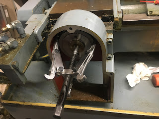
Anyway, time to remove the pulley. Luckily one of the pulley pullers actually fits in the space available.


Luckily it didn't fight me.


Missing detail - I removed the Z axis (long) ballscrew). The thrust bearing is at the headstock end, simply held down by 6 bolts and 2 dowel pins.

The ballnut is completely gummed up with nasty grease. There's no lube (oil) connection, so it presumably relies on grease for lubrication. Either way, it seems to need some degree of cleanup.


Spindle nose:
Let's have a look under that spindle nose cover and see what we are dealing with. 


Underneath the cover, it looks in decent shape. There's some form of taper seat and 12(!) threaded holes. I'll need to figure out WTF sort of interface this is.


Enclosure removal:
I think the time has come to remove the main enclosure. I've removed enough of the cables, hoses, fixings etc to be able to lift it off so I can actually access all the gubbins. Trying to get to it through the holes in the enclosure is a waste of time.

Removing the handful of fixings allows the enclosure to simply slide / lift off.


That nasty yellow colour is the primer paint.


Ready to go


Just needed another pair of hands. Here we go:


That's better - let the dog see the rabbit etc:


Pretty much everything structural you can see here is actually cast iron. No wonder it's so F heavy, although it's lost a LOT of weight over the last couple of days.


Cross slide / X axis:

Similar looking servo motor, underslung beneath the saddle here. I'd never have got to this without taking the enclosure off....


Quick cleanup before removing the cover and letting all that brass swarf in.


That's better.


Very similar arrangement here. Bloody great cast iron bracket to hold the encoder...


Again, luckily the pulley puller fits in and does the business.

The ballnut is held by 4 cap heads and 2 dowel pins. The pins have a female M5 thread, so I can extract them from above.


Then the cross slide can be moved freely by hand.


The sliding faces are in decent condition. The hand scraping is in good shape, as befits a fully enclosed slide that has had relatively little use.


Even the top face of the ballnut bracket has been scraped in.
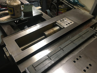

The ballscrew is captive until I can remove it from the front thrust bearing. It's actually too long to clear the rear bore and simply lift out.


A closer look at the bed ways. They look pretty good. 
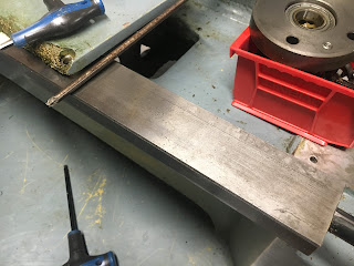

Dear god - what have I done!


I'm running out of space with all these enclosures, covers etc.


Right, that's it for the moment. Until next weekend....

Saturday, 19 February 2022

The weight loss program continues...

Bloody hard going, this. But finally I've stripped out all the gubbins from the cabinet.


Removed the back plate from the cabinet, to make it a little more manageable. Then unhooked it from The Silly Great Framework. It only just fits through the gap between the SGF and the shelving unit.


Next, to remove The Silly Great Framework itself. As you can see, the sheet metal work enclosure is self supporting, so apart from the hinged door at the headstock end, there's no longer anything relying on the SGF. 


I'll need to reroute a couple of hydraulic hoses.


So off it comes. Not quite as silly heavy as I'd thought it would be.


Note a few connections for the spindle encoder before I (have to) chop the crimps off to get the cable out of its conduit.


Now let's tackle the effing great DC spindle motor. What a beast.


There's some form of taper lock feature in this bloody great cast iron pulley. Luckily there are also a couple of threaded holes for extraction. These seem to be 3/8" UNC and I can reuse some of the cabinet fixings for that purpose.


There. Now we can see the Siemens motor. There's also a centrifugal cooling fan with intake filter mounted on top, just about visible at the back.


Out it comes. The (cast iron) motor carrier and straps are F heavy duty. 


Come along now...


It's like a large dog out of its kennel


That's better - most things are removed now and with the cabinet and frame removed, it's a more sensible looking width now. There's plenty of room for a 3-4kW induction motor to fit in.

That was bloody hard work. I will need to get the scrappy round to collect all this old iron and steel. That and the Silly Great Framework. You can see the horrid orange doors, back plate etc in the background. 

Next - let's have a look at the axis motors. For that I may need to bring the carriage closer to the tailstock end. I may be able to use a bench PSU for that.

Sunday, 13 February 2022

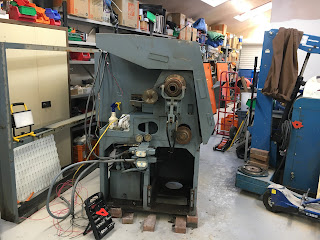
Tree UP-1000 CNC lathe - plan of action - stripping out the control cabinet

So, what's the plan, Fatty?

I've had a good sniff around now and got a pretty good idea what it looks like and how it works. And here's what I plan to do:

  • Strip out the control cabinet. There's nothing in there that I could possibly want to reuse apart from some DIN rail and possibly some barrier strip / terminal blocks.
  • Remove (and scrap) the cabinet.
  • Remove and scrap the massive steel framework.
  • Remove and scrap the DC brushed spindle motor. I will simply use a 2850rpm induction motor of around 3.5kW with a 1:1-ish pulley ratio and a Yaskawa VFD.
  • Possibly retain the hydraulic pump and controls that operate the collet closer, tailstock and ATC turret. Changing these over to electronic (or pneumatic?) control might be reasonably easy but would still require hours of pissing about. If the motor can be persuaded to run from a VFD, I could save a lot of ball ache. I have a couple of 5.5kW Extravert VFDs that could run a static-ish pump load.
  • Retain the existing (presumably) brushed DC motors and (ballscrew mounted) encoders. Use the same cncdrive DG4S160-35 that worked on The Shiz, at 240 Euros for the pair. I can rewind a site transformer to get myself a 120Vdc bus voltage, as before.
  • Use either LinuxCNC or Centroid Acorn to run the controls. I've persevered with LinuxCNC on the Bantam so far but TBH, the Acorn would just be a simpler solution and require less fucking about. The main downside would be the $300 cost of the wireless MPG but the rest of the system is actually fairly well priced. Including the pro licence and the MPG, it would come in at $800 including shipping.
  • As for the ATC, it seems to require very little external control. There's a simple position feedback (encoder), a home switch and a solenoid for operating both the turret lock and advancing the turret. Given how simple this is, I may try powering up the hydraulic pump and firing up the solenoid to see what happens. I'm expecting the lock to withdraw and the turret to index but I'm not sure. The solenoid seems to power the hydraulic motor AND the turret lock. I'm wondering if there is some sort of hydraulic valve that controls the motor according to the position of the turret lock. The service manual I ordered from the US ebay site will hopefully tell me that when it finally arrives in a couple of weeks (hopefully).

So off we go:

Firstly, we need to let the dog see the rabbit, so let's heave that door off. The other one is inaccessible, so will have to wait until I can remove the cabinet and drag it out of the way. While I'm at it, here's the control panel housing, sans control panel, such as it was:


Nice orange colour. The hinges are welded to the main cabinet, so out with the angle grinder:


It's hanging on by a thread almost...


There. Gone.


I'll be keeping the nameplate and refitting it somewhere, later on, along with the Matchmaker sticker from the side of the cabinet.


Right - out with the old gubbins:
  • Siemens drive.
  • Servo amps.
  • 3-phase transformers.
  • Mains contactors.
  • Forest of control relays.
  • Controller.
  • Miles of cables and wires.
  • Dozens of cartridge fuses.
  • Dozens of terminal blocks.
  • Metres (yards?) of trunking.
  • Paper tape reader.
  • Several fans.
  • 2 PSUs.
  • Ground and neutral commoning strips.
  • 3-phase transformers (x2).
  • ...


Bloody hell. The guy had better not want his lathe back in working order is all I can say.

To be continued....

Bantam CNC - final homing and backlash optimisation (phew) - index homing no more.

There's still some work to be done on this homing accuracy business. Let's see if we can crack it finally. The decision to use the C...