What up, Fatty?
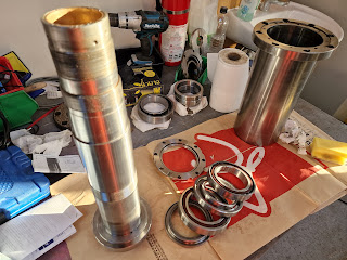
I getting even more frustrated at my inability to remove the collet cartridge from the nose of the spindle. Even with the spindle removed from the machine and free of its bearings, I'm not closer to removing the damned thing. Seems to me that I have 2 choices here, assuming that I'm not prepared to let it remain:
- Mount the spindle in the Bantam and machine (ie hard turn) the cartridge with carbide tools. This assumes that there is enough room to mount it in a chuck and get tooling to the internal bore. This in turn assumes the fixed steady is suitable (large enough) to be used to support the free end.
- Leave it in place for now and plan to machine it out in situ once the machine is up and running. ("physician heal thyself" etc).
TBH, I favour the former choice, as I'd like to get this behind me. However, there are pros and cons to each approach:
- Even a cursory glance shows that the fixed steady isn't going to be able to support the spindle in one of its original ball bearings, so there will be a high speed contact between the steady fingers and the ground surface of the spindle where one of the bearings is seated.
- There's also the matter of recommissioning the LinuxCNC controls for the Bantam which I had to partially dismantle to get the Tree into the workshop.
- On the upside, it would allow me to clean up the surface rust on the spindle nose.
Let's see how I get on with recommissioning the LinuxCNC system on the Bantam. Then I can revisit my options and make a decision.
Will the Tree spindle fit on the Bantam?
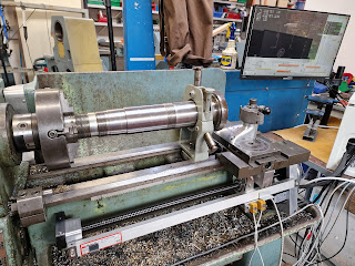
Well yes, for starters the spindle will just fit on the Bantam with the fixed steady in place. That's helpful....
...although I'll need to remove the tailstock if I plan to actually machine anything...
....and flip the solid toolpost base 180 degrees to gain a last few mm. This looks almost workable, so let's see about getting the LinuxCNC control system running again.
Managed to get LinuxCNC gmoccapy running again once all the wires and connectors were reconnected. And once I'd run Linux 5.10 rather than 5.4(!!). I must get rid of all the startup options, as the default (v5.4) won't run LinuxCNC due to timing issues with the Mesa cards. Presumably something to do with the different kernel.
Let's try to get the spindle set up on the centreline. Luckily, the live centre which came with the Tree has a conical nose that fits into the mouth of the spindle, so I can get the spindle on centre within the steady.
Getting the spindle set up at the 4 jaw end.
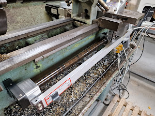
Telescopic ballscrew covers:
There will be some nasty swarf generated here and I'm seeing flecks of swarf and crap being attracted to the ballscrew already. So time to clean up the ballscrew with WD40 and copious lengths of tissue. Then clean up the Chinesium telescopic leadscrew covers and fit them.
There. Not quite your high end product but it will keep crap off the ballscrew.
Let machining begin!
Ready for action.
A couple of tip changes later and we are under way. The start was particularly hard but once I got under the skin and figured out the best feeds and speeds, the tips started to last a little longer. I must buy some tips that are intended for hard turning, as this could work out being an expensive job and my selection of CC** inserts is disappointingly limited.
Getting there....
I don't want to completely roast the spindle. Although it's a fairly even and symmetrical heat source, I'll try to keep the temp under 50C or so.
The collet gives an idea of the metal removed so far - it used to be almost flush.
I'll stop there. And a quick cleanup with some 180 grit and a white scouring pad has removed much of the rust and crap.
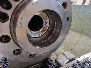
Making a start on the internal bore. It's actually a lot easier than the facing work. I'm guessing it wasn't as well hardened. I'd expected the boring bar to have hada harder time of it. Having said that, I've got a lot to remove before I get close to where I expect to find the actual spindle bore itself. Let's keep cracking....
God this is taking forever. I can't load up the machine much due to the bronze fingers on the steady either being loose or potentially so tight they bind. Ideally I'd have had a rest with ball bearing contacts but here we are.
Ooops. The spindle is gradually working its way out of the chuck. Time to realign.
Another hour or so later, the cutting sound changes half way down the bore. I suspect the nasty wobbling is due to a very thin wall thickness, so perhaps something is about to emerge from the mystery zone. Let's keep going and see what develops....
Aha - a breakthrough at last - literally!
I can pull this remaining shell out with cutters
Luckily, the body of the cartridge is relieved, so I've been able to machine it away without touching the bore of the spindle. Now there's nothing actually holding the front section in place, so it should come out. No way to grip it, so let's keep making skim cuts until something happens, meanwhile ensuring I don't actually make contact with the spindle bore....
Ping - that's better. It's a taper, so was simply being held (firm) by the preload in the tapered bore. Now I can see the actual (tapered) bore of the spindle nose finally. It makes sense to have a tapered bore, as a stepped, parallel bore wouldn't give a controlled location unless it was a press or interference fit.
I can get a tool up to the remaining body, to machine the remining body back. But as there's no step in the bore, it can only be held in place by crud, so there should be no need.
...so let's give it a tap with the mallet.
Woohoo. That shifted it - finally!
Here's that tapered remnant from the front of the cartridge.
...and the rear end of it. Everything in between is now reduced to a bundle of swarf.
That seems to be a lubrication hole and was aligned with the mystery hole in the spindle nose face.
Well?
So finally I have the spindle sans collet cartridge. Although it only took a few hours, that took care of most of my free time this weekend. Annoyingly, there was nothing that could have been holding this in position other than the tape bore itself. I gave it copious volumes of WD40 and some hefty clouts delivered along the bore of the spindle but still failed to shift the thing. I guess years of hydraulically applied collet closing force will have lodged the taper firmly in its seat.
So in conclusion, the collet "cartridge" was no more than a relatively simple bush with an externally tapered nose and a 5C bore. The 5C collet would poke out the back and be screwed into the drawbar. I might have pressed it out the front of the spindle if I'd been confident it had no locking collar holding it in place - and if I had the tools to do so without buggering anything.
But at least I have a clear through bore - which measures exactly 2" (50.8mm). Not bad for a high speed lathe.
What next?
So - time to clean up the bore and reassemble the spindle assembly. Then the task of trying to refit the spindle cartridge back into the head. I know from experience with The Shiz that this can be very tricky when the finish is a very close sliding fit....