I also want to check out some of my other cutters on steel, having only cut aluminium to date. I have several carbide cutters now, courtesy of ebay etc, some of which seem to be of professional quality ie will probably get snapped by me in no time.
At this point I need a tool setter ("assembly support" in fact) but I'm not about to cough up for one.
So it's time to model up something suitable. I already have a model of the basic ISO40 tool body, having previously looked at the possibility of using BT30 tooling with the ISO40 drawbar (the conclusion is that it's not really a possibility at all), so I can build the tool setter around it.


There's basically a surface with a hole for the taper and 2 drive dogs. The taper hole would ideally(?) extend for most of the length of the taper but this would require a substantial piece of steel. I'm also a bit uncomfortable with the way these tools are generally not held in the tool positively, so I fancy having a threaded retainer to hold it while I tighten the tool. And being a tool "setter", it may be helpful to be able to mount a DTI on the front face so I can measure the tool length from the gauge surface (or a surface that is close and consistent enough for my purposes).
So rather than go for the full depth taper, I will use a piece of 1" x 2.5" stock (yes, imperial dimensions, bought in Canada) with an extension to reach and support the threaded end of the toolholder. This will be fabricated from 3 basic pieces and simply bolted together. I don't have the welders commissioned yet and threaded fasteners should be fine.
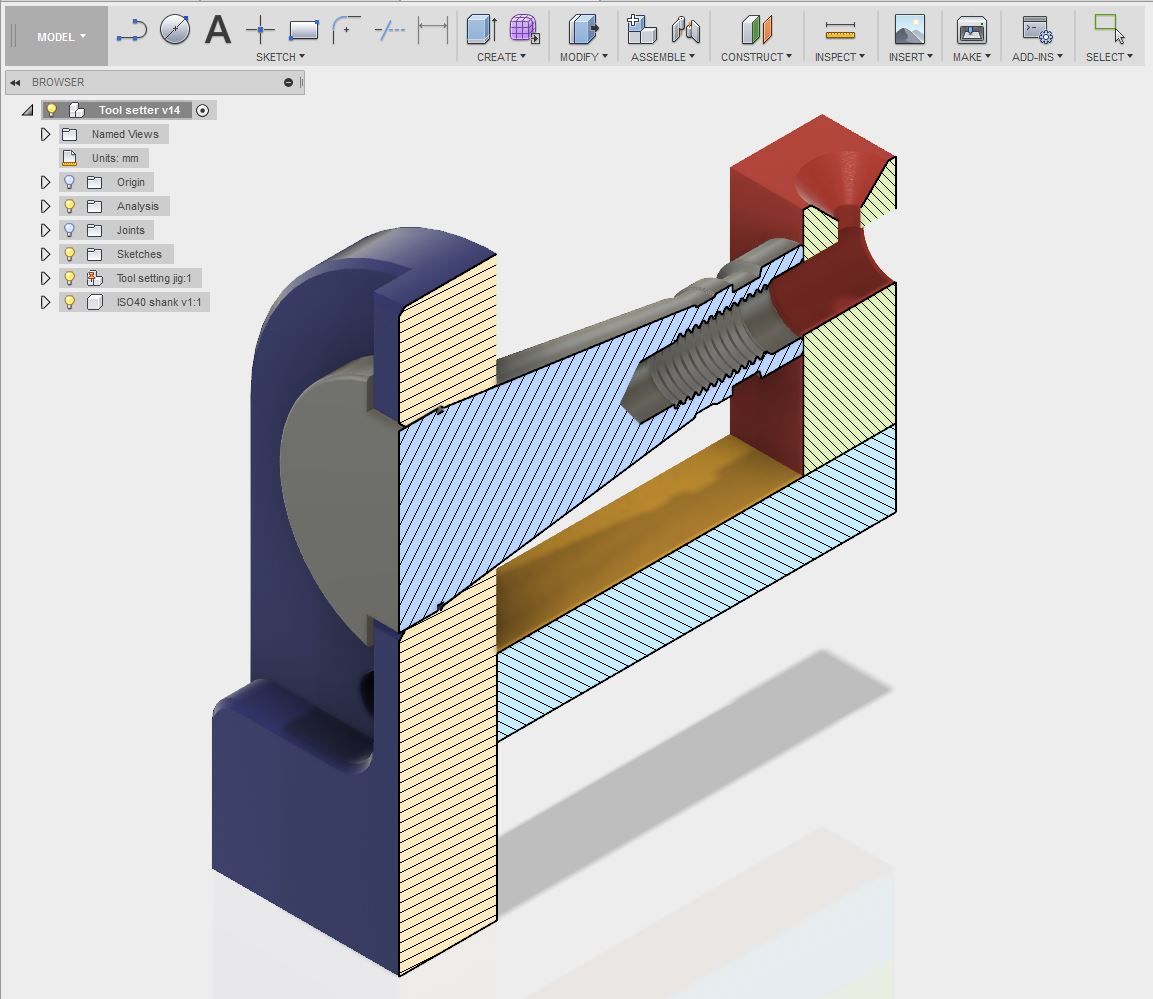

I've shown the corners rounded and chamfered, to reduce the risk of skinning my knuckles and worse. The flat surface at the front bottom will be for holding in the vise in the orientation shown.
This should allow me to try out a few operations using my carbide end mill and probably the BAP300 12mm indexable cutter with steel cutting inserts. With a 0.8mm radius tip, I should be able to get a vaguely reasonable finish in the conical bore if I specify small step-downs.
In terms of stock holding (in the machine vise), the bar stock is quite a bit longer than the model, so it will be easy to hold and I can cut off the main body after machining.
That's the plan as it stands today. I'm sure it will evolve before any metal is cut....


No comments:
Post a Comment