I posted about the saga on the Model Engineer website, so no need to go into detail here. I picked up a few more toolholders over the next year or two, almost entirely from ebay in the end.
Although the numbering systems used is fairly confusing, I soon learned that there are several sorts of toolholder based on the 30 size taper:
- ISO30 / INT30 / NT30 with parallel shank and a metric (M12) thread
- NMTB 30 with parallel shank and an imperial thread (1/2-13 in USA, probably 1/2" BSW in UK)
- BT30 with no parallel shank (intended for pull studs)
- Possibly various "shankless" close relatives to the BT30 (SK30?? etc).
In my case, the original drawbar was metric, so perhaps the system that came with my machine was technically ISO30, not NMTB30. However, it only came down to the thread on the drawbar. This was probably imported from China or Taiwan into Canada, so not surprising that it has quite a few metric threads on it.
With the new quick change system in place, it seemed I could use either of the NMTB or ISO shank tools. However, it finally dawned on me that BT30 tooling could also be used just as easily if I simply fitted a longer pullstud. And given that the pullstud is to my own design , I'd have to make or procure them myself. BT30 tooling sees to be more widely available and less expensive, although it still works out costing more than 40 taper tooling despite its smaller size and reduced material cost. This is almost certainly due to BT30 being used on more modern / industrial machines than the old shanked tooling.
The missing part required to convert ISO30, BT30 etc tooling to make it suitable for my quick change system is the pullstud. Although it's a fairly simple design, I'm really not set up for making runs of 20-40 pullstuds, either temperamentally or in terms of my workshop facilities, so I looked at getting them made by a supplier. There seem to be many workshops offering to undertake small runs of CNC components.
I drew up both versions of the pullstud in Onshape. This was emerging as an exciting new product with the potential to be a cost-effective solution for hobby users. I was involved in the beta testing of the early product and found it to be reasonably easy to use. The main downside was the limited storage available for free and the eye watering cost of the various add-ons, such as the 3rd party CAM apps. Fusion 360 came along not long afterwards and must have put a pretty big hole in their business model. Either way, it wasn't long before I made my excuses and left for Fusion 360. This is the "long" version of the pullstud:


Onto today (actually yesterday now), and I've been looking at the lathe and manual milling machine recently and feeling guilty at the way they've been neglected during the recent move from Canada and the workshop build. I've needed to use them for small jobs and it seemed a good time to do something about them.
Seemed like a good time to dig out the various tooling I've acquired over the last 3 years and unite them with these fancy new pullstuds. For one thing, it would be helpful to know that they actually work. Back then I did some careful measurements to try to ensure that the long pullstuds would simply screw in and work. It wasn't possible to achieve that with the short pullstuds, as the standard shank is too long to coexist with my collet system, so some machining back of the NMTB / ISO shank was always going to be necessary. Which was another reason for preferring the BT30 tooling in the first place.....


Bugger. The highlighted 18mm diameter wasn't right. I don't recall the exact circumstances but I either guessed the dimension, read it incorrectly from the model or typed it in incorrectly. Either way, it should be 16.5mm and it says 18mm on the drawing. The stud simply won't fit up there if it's too big.
These are made of 1045 carbon steel, through hardened to HRC 56-60, so machining is possible but not entirely conventional. Using carbide tooling and with the lathe at maximum speed (1600rpm), it's simple enough to machine hardened steel. The material is melted as it comes off due to the high cutting speeds - if you can get the surface speed high enough.
First - make up a threaded adaptor to hold the pullstud for machining:

 Finished and ready to go:
First - make up a threaded adaptor to hold the pullstud for machining:

Turned down and drilled out, now tap M12:


Sorry about the way I was dancing about at the end here. Those bits of burning swarf hurt like hell when they land on your arm.
I machined 10 of each of the studs by setting up the carriage stop (to stop the tool a fixed distance away from the chuck) and cross slide stop (for diameter). Job done:


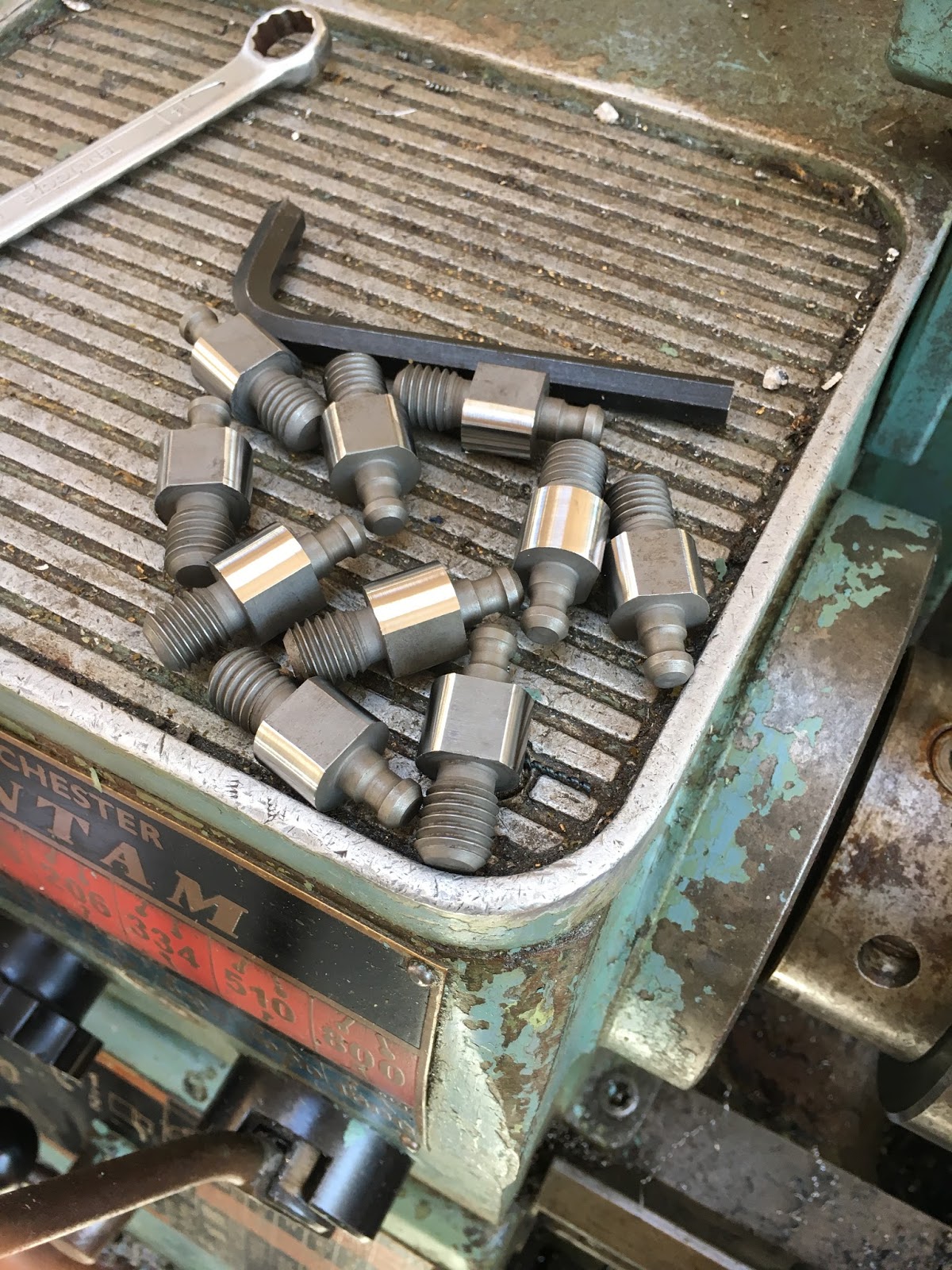
The machine ends up covered in a sort of funny bum fluff:

Here are a few ISO30 and BT30 tools with their new pullstuds fitted. The drill chuck has one of the original hand made pullstuds. Below are a BT30 (middle) and ISO30 (bottom) :


No comments:
Post a Comment