Yesterday I took the Z axis ballnuts apart to see if there was any means of adjusting out backlash in the ballscrew assembly. Indeed there is, although there was barely any backlash take up when I tightened them together with the locking strips removed. So clearly the backlash was elsewhere.
I reassembled the ballnut / yoke assembly - nothing to be done in there.
I'm no metrologist and that's not by accident - it's not my favourite activity. However, I have the basic equipment that will at least give an indication what the source of the backlash is. I have 2 DTIs - one is a Kurt-branded Chinese thing with 1" of travel and 0.001" graduations (being Mercan, it's imperial) and a Swiss "Baty" brand with 10um graduations and 0.8mm total travel. 0.001" is about 25um, so the Baty has slightly higher resolution - but not by much. I should get a better one.
With the DTI clocking axial movement right next to the ball nut, there is no discernible movement of the needle as the ballscrew is turned. That agrees with the tiny backlash seen when the ballnuts were removed. Despite what I said yesterday, the most likely explanation is the slop between the quill and its bore in the head. And sure enough, when I measure the axial backlash at the quill end of the ballnut yoke, it is measurable. So the quill is not moving in a simple axial direction. This machine had 20 years of (careful) use.
Furthermore, when radial backlash is measured at the nose of the quill, I can see the best part of 40-50um. Note that I'm doing this with the quill near full extension. And when I draw the quill right back to top position and measure the radial backlash, it is almost immeasurably small.
The way I measured the radial backlash was by driving the quill down onto a large, hard rubber mallet. This loads the ballnut, resulting in a torque on the quill and taking up any radial backlash.
The rate of wear of the quill and also the radial backlash at the quill nose will be significantly higher the further out the quill sticks. And sure enough, as noted above the measurements appear to confirm this, even though they are very basic. The lesson is fairly obvious and hardly a revelation - minimise the quill stick out at all times, particularly when accuracy is required.
It's curtains for the old beast!
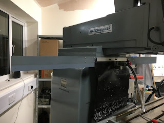
I took delivery of my 3mm thick black neoprene sheet today: 1.4m wide and 3m long. So I dug out the frame that the original curtains were suspended from. The 3 sections are held together in line with M4 screws. The centre section bolts to the machine body. Then the rubber curtains are fastened to the side sections by the 2 thin strips. There is already a slideway cover behind the table which will be left in place.
Also refitted the giant chip tray - as well as the optional power drawbar, this machine came with the optional chip tray and presumably the curtains were part of that system. Just a pity it didn't get the automatic tool changer too....
Given the rather fetching stream of swarf I managed to generate on my first metal cutting trials, the chips aren't simply going to fall on the table and need sweeping up. I need to catch them, to prevent them streaming all over the shop.
This is the original position for the rails:
I took the chance to reposition the top of the curtain slightly higher, right up against the bottom of the ram assembly. The neoprene is wide enough for this. It simply required a couple of new M6 tapped holes and a hole in the existing rear slideway cover for the coolant hose.
Job done and it looks good. Next job will be cutting and fitting said neoprene curtains.....


No comments:
Post a Comment