Monday, 30 December 2019

Playing with the Fadal ATC

This thing requires compressed air (to operate the arm actuation piston and the claw), 24V (for the forest of relays that form the control "logic") and 110Vac (for the indexing motor - Geneva plate etc).

I can cobble this up fairly easily (as indeed I have done before) and operate the thing in manual mode. The auto mode would require something appropriate at the other end of the interconnect cable, either sending 24V signals or more likely some switch contacts. That's not about to happen.


Here's the arm doing its thing. As noted previously,


And here's the Geneva wheel thingy doing its business. Very impressive.


The successful operation of the tool changing process his thing is entirely dependent on the mechanism within the arm. Ingenious though it my have been thought when it was devised, if it's buggered or simply worn out, any effort I expend getting it cobbled up onto the machine and connected up with some form of modern controller (Arduino - or directly using the Acorn?) could be wasted. 

What next, Fat Boy?
Yeh, so what? Well for one thing, the whole chebanc weighs several tonnes. Managing to get this thing offered up - and finally fixed to the side of The Shiz could be a bit of a nightmare. And half of the guts of this thing are not long for this world. Why's it so damned heavy?

In practice, I only need to mount the arm mechanism alongside the spindle of The Shiz and (if the basic mechanism can be made to work consistently) the tool carousel / chain thing could then be mounted on a shelf next to that. 

As for the baseplate, it's the best part of 3/4" thick and despite being made of loominum, would chop your feet off and make a hole in the ground if you dropped it on them. Admittedly 40 taper tools are fairly heavy but even so, it seems a bit OTT. 

Then there's the whole forest of relays / solenoid tree / giant pneumatic piston / front panel etc. Most of that can simply be junked and the arm operated by a motor / reduction gearbox. Currently, the arm is operated by a 2" diameter piston with an in-built damper piston. Given that the stroke is something like 6", that makes the whole piston assembly the best part of 18" long and it even sticks out the back of the cabinet.


Said solenoid tree:


Relay forest and front panel: 


Most of that stuff could go straight in the skip, including the front panel itself.

This is the machine side of the cabinet:


Keep your nadgers away from this when operating in manual mode. Of course, when bench testing it, you will be standing in just the right place....


And this is where it's supposed to be fitted.


Something to think about....

Saturday, 14 December 2019

Fadal ATC + Acorn expansion board??

The History:
In May last year I was offered a genuine Shizuoka-approved ATC by Mike "Steamwise" who lives nearby. He'd probably concluded that it wasn't worth the ballache involved in setting it up on his Shizuoka AN-S. Naturally I couldn't prevent myself loading it up into my car and further cluttering up my already-chocka workshop. Given the insufficiency of spare I/O on the Acorn installation used on my own Shizuoka AN-SB, it has been sitting there ever since. True enough, I actually connected it up on the bench and managed to make it function in manual mode but that's as far as it was going to go until I was able to find a way around the IO famine.

As seen last weekend, Acorn have now released their eagerly-awaited expansion board (ETHER1616) that provides an additional 16 inputs and 16 outputs per board (with a potential of at least 3 boards per system). On the face of it, that should do the trick, not least as there seem to be some ATC functions available from the Acorn website and forum. Sounds simple enough?

Stocktaking:
Yes, it seems simple enough. Or perhaps too simple for The Stupid Fat Bloke who always makes a point of getting involved in stuff like this?

Fact is, the ATC unit is f*cking massive and heavy. And as it is, the main machine itself already weighs around 3 tonnes and is at the limit of what I can move. Given that I plan to move house and workshop next year (if plans go smoothly), bolting loads of heavy scrap to it doesn't seem the clever thing to do. This anxiety is tempered by the fact that we actually built the workshop after said machine had been moved onto its concrete pad. I haven't weighed it but I think we are talking over 50kg on a good day, probably more by the time the cover / door is refitted and the tool chain is refitted. 

I had a close look at the thing back when I first got it in the workshop, so I have a fair idea what I am looking at. Here's a recap:


Solenoid block to control the large piston that moves the claw, as well as actually opening and closing said claw.


It's all done with relays and a series of cams that triger an impressive array of microswitches (top left of the photo below):


Nice old front plate. This shows it is one of the very first models. Later ones didn't mention Fadal.


This is the face that bolts to the side of the machine. 


By default, the claw sits next to the spindle nose. When open, it clears the quill (just!).


Vicious looking thing!


This is the side it bolts to. You have to mark out the bolt positions yourself but of course I have no drawing to work from.


I've wired it up for bench testing again, so I can get a feel for how it works. Requires 24V for the various relays, solenoids etc and 110Vac for the turret motor. And a compressed air supply for the pneumatics.


So what's the problem?
Well, several actually:

  • It weighs rather a lot, and really there's no obvious reason for it. Fitting the damned thing may be not only hard work but quite likely rather hazardous too.
  • The pneumatics are pissing oil everywhere. The drip lube oiler seems to be out of control and said excess oil emerges all over the shop (literally) from almost anywhere there is supposed to be a seal.
  • The tool chain / turret / Geneva plate motor thingy requires 120Vac, which adds a layer of complexity and hazard I'd prefer to do without.
  • The main air piston is a scary thing, apart from being the biggest culprit when it comes to oil spreading. It's also rather crude in terms of being able to control the speed of  actuation. I'd like to drive this differently.
  • The relays / microswitches / pressure switches etc aren't likely to be the most reliable components, especially after several decades. 
And what are you thinking, Fatty?
Well...
  • The actual claw mechanism seems to be an ingenious(for its time) all-in-one design that lowers the tool, inverts it and swings it around, before dropping it down into its "cup" on the conveyor chain. Assuming this thing isn't completely fucked after all these years, this is the only critical part of the ATC that needs to be bolted securely to the machine. Fair enough, the tool conveyor thing needs to be reasonably solid and consistently positioned but that doesn't require it to be made of solid aircraft carrier.
  • I don't like the look of the electronic electrical bits.
  • The pneumatics appear to be geography.
  • In fact, I could jettison most of the gubbins altogether. 
Before going Over The Top, I need to investigate further. How do all those little microswitches and relays get involved in the movement? Am I missing something?

Time to flash it up and look closer. If I can avoid disembowelling myself, I may learn something helpful.....

ETHER1616 bench test

What?
I'm not expecting to find any issues when I connect up the expansion board to my current Acorn system but it would seem rude not to check it out, seeing as I had a good snoop around the thing last weekend. As well as the main expansion board itself (motherboard?) with its 16 additional inputs, there are also 2 relay boards for the 16 additional outputs. Looking at the setup guide, it should be fairly quick and easy to wire it together and toggle some inputs and outputs.

Here we go. Even The Stupid Fat Guy would be able to connect this thing up without cocking anything up. No magic smoke, no scratchy head.


And toggling the outputs is simple enough if you go to the diagnostics page (Alt-i), select an output (using the arrow keys) and toggle that output (Ctl-Alt-f). The green LED of Output 34 is toggled on on the screen and on the relay board.


Testing the inputs is even simpler if you have a flying lead like me - or by inverting the input on the diagnostics screen (Ctl-Alt-i).

Not entirely sure what I was hoping to prove, other than to gee myself up a bit. Who knows, I may even pull my finger out and do something with it next.

Oh yes, there's that Fadal ATC for The Shiz to think about.....

Thursday, 12 December 2019

Centroid ETHER1616 expansion board

Parkisonian affliction?
Yet another mouse accident / finger twitch inflicted me last weekend when innocently surfing the Centroid Acorn user forum. I need to find out what is causing this before the Domestic Manager twigs what is going on.

This time, I came home 5 days later to find a parcel outside the back door with some stuff from Centroid in the US. 


This is the much-awaited Acorn expansion board, aka "ETHER1616".


What's an ETHER1616?

It's an expansion board, aiming to improve on the rather limited IO (8 inputs and 8 outputs) of the basic Acorn board, so-called because it is connected to the Acorn by Ethernet and provides an additional 16 inputs and 16 outputs. Up to 3 boards can be connected up simultaneously, providing up to 48 inputs and outputs. The IO are all optically isolated from the main controller.

ETHER1616 setup guide


In fact, the expansion kit includes 3 PCBAs, namely the main motherboard and 2 relay boards. The relay boards connect to the motherboard using (supplied) IDC cables. There's also a dedicated PSU (from Meanwell), a TP-Link 10/100 Ethernet switch and some shielded Ethernet cables, plus a few bits and pieces in a bag, which turn out to be a choice of plug-in SIP resistor arrays for input pull-up / pulldown, depending on the system voltage you are using (12V, 24V etc).


Taking a closer look at the motherboard:


Like the Acorn boards themselves, it seems the connector headers have been hand soldered, presumably by Centroid in the US. This leaves flux residues, so clearly it's not no-clean flux and they haven't seen fit to clean the boards afterwards. Not the end of the world (that's next week) but I prefer to see this cleaned off myself.


Overall it looks pretty well executed. The green edge connectors are 2 piece pluggable jobbies, so you can remove the board without having to unscrew all the terminal connections. The white connectors are for the relay board connections. There's a 7 segment LED display and some sort of programming / debug edge connector that I assume we won't be using.


What's on the motherboard?
In no particular order:
A Microchip PIC32MX350F256L 32-bit micro. Seems a bit OTT?:


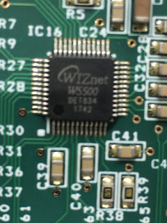
At the bottom of the picture below, there's a Wizz W5500 Ethernet controller with its own crystal (and an EEPROM?). At the top left is a line driver and the black block is a DC-DC converter. 


Closer view of the Ethernet controller:


And here's a closer look at that DC-DC. Generates 3.3V from 7-28V input. As there are only 3 pins, it's clearly a non-isolating buck (down)converter.


The SN65C3222 line driver receiver runs what is described as "SERIAL 1" but doesn't seem to be used in a user setup. Perhaps it allows board testing without the need for a network (Ethernet) connection. Can't be bothered to trace the path to see what it connects to but you might expect the PIC to be involved.


These devices are ACPL-244 opto isolators for the various IO signals


This is the connector for one of the relay boards, next to some MC74AC125 tri-state quad buffers


Yet another Recom DC-DC module - there are 3 of them in total. Presumably not a cheap solution but simplifies the design process. They are pin compatible with the 78xx linear regulators but being switchers, they aren't anything like as lossy (hot). This one outputs 5V at 1A. Farnell pricing is around £2.50 each in 250 qties.


This is a 25AA02E48 (2kb serial) EEPROM from Microchip. Seems to be associated with the Ethernet driver but not sure why, as the W5500 app notes don't show the need for one. 

The edge connector is presumably for talking to the PIC during s/w development. And here's the Microchip serial EEPROM again.


Tested 5th November 2019 (Bonfire Night!). Hope that's not a bad omen...


Relay board(s):
...to follow...

Saturday, 7 December 2019

Centroid CNC12 - 4.20 beta test

CNC12 beta:
Centroid have just released v4.20 of the CNC12 control software as a beta version. This hoovers up a few bug fixes, slickens up the Wizard interface and incorporates support for the newly released ETHER1616 expansion board.

The only bug I noticed in the previous release (4.18) was the unintended (slow) movement of the table when the wireless MPG was used to adjust the spindle speed. This was confirmed as a bug and appears to have been fixed in this update.

Installation:
The process is fairly simple and explained clearly by Keith in the setup video:


For upgrades from a previous version, the second method is best:

  • Save a report from within the current, stable version.
  • Rename the default directory (to save the whole file structure, config files etc) - I saved it as "cncm - 4.18 stable", consistent with my previous convention.
  • Install the beta software from scratch. Download from here.
  • Restore the report from the previous version (4.18).
  • Start up the Wizard and select the option to use the std PLC code.
  • Save the Wizard config and create a backup report.
Before:

After: 


The experience:
Various restarts of the Acorn and the CNC12 software are required but the PC itself doesn't need any restarts.

Compared to previous experiences, this has been relatively (in fact, almost entirely) pain-free. Back in the days of 4.10 - 4.14, each "upgrade" would typically render either or both of the tool setter and touch probe useless, requiring several hours of buggerage to sort out.

I've done no serious level of testing but at first sight it seems to be functioning correctly:
  • Homing
  • Tool length offset auto setting (using touch off device)
  • Part probing (using the Renishaw probe)
  • MPG jogging, functions etc
  • Didn't actually check the MPG "spindle / jogging interference" bug but they claim to have fixed it, so I expect it is.
I must bear in mind that this is beta software ie they are expecting to find and fix bugs before making a formal release. However, I'm not planning a "production" run any time soon. Besides, it supports the ETHER1616 expansion board*


*more about this later....


Sunday, 27 October 2019

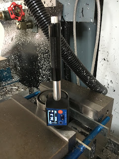
Chinesium Leeb (rebound) hardness tester

Another mouse accident:

I bought one of these portable Leeb hardness testers from AliExpress. Arrived fairly promptly but of course TNT decided to help themselves to my funds on the way into the UK.

I've had a chance to look at it now. The carry case it comes in is a Chinesium copy of one of those “Pelican” travel cases, although I suspect the water / dust proofing qualities may have been lost along the way. Nonetheless, the stuff inside seems to be reasonable.


Yes, the Leeb hardness scale is actually very simple. It’s just the ratio of the impact and rebound velocities, from which some clever dick materials guys (Leeb and Brandestini) deduced a relationship to hardness. 


As for the method of acquiring the data, “a magnetic impact body permits the velocity to be deduced from the voltage induced by the body as it moves through the measuring coil.” Sounds simple enough – and what you might expect. The energy absorbed in the impact gives an idea of the plastic deformation or relative lack of it. If you prefer a more mainstream hardness scale, the tester simply translates the Leeb Hardness value to Rockwell C etc. 

If you try to measure the hardness of a coin, the surface features seem to prevent correct operation, presumably due to the small size of the test ball embedded in the relatively large moving head getting fouled in the valleys etc of the surface. Similarly, if the body is small (ie not much more massive than the moving test head) and not supported firmly, the reading suffers (suggests a lower hardness than actual) due to the loss of rebound.

Thought I'd have a go at measuring a few items although unfortunately I don't have any reference pieces of known hardness or other hardness measuring tools to cross reference my measurements.

Let's check these out and see if the readings seem remotely plausible, despite the lack of traceable known references. I'll be interested to see how the pukka Korloy toolholder compares to the Indian (Glanze) equivalent. It's my unfortunate experience that crashing the Glanze toolholder results in the tip of the body going plastic in a non reversible way. In contrast the Korloy grooving toolholder (not this actual example) will fracture if you really crash it properly, rather than bend or flow.


So here we are - ~HRC 35 for the Korloy


And ~HRC22 for the Glanze. Sounds about right - piece of shit toffee.


The body of this ISO40 toolholder is as hard as witches tits. Files bounce off it. It's actually the one that came in The Shiz. Sure enough, we see HRC 52.3


This pullstud adaptor (my design) was made by Funwick in China when I worked there. The test report claimed HRC 56 - 60. They have worked fine but oddly enough(!!), I'm seeing HRC 34.8. That's probably not a bad outcome anyway, as I don't want a component like this to be too brittle.


The "hardened" jaws of the Arc Eurotrade vise suggests about HRC 36, which seems reasonable.


The hardened inner race of this HSK bearing reads around HRC 51. According to Schaeffler, bearings are typically in the range HRC 60-65. Seems to be reading low, given that these are almost certainly through hardened ie shouldn't matter where 


Indicated HRC 56 on the table of The Shiz....


I set it to a different scale that is more suited to CI but The Stupid Fat Bloke took this photo and he didn't think to make the display fully readable. The scale indication (HRC, HRB etc) is partially hidden at the top LHS of the photo here.


It's not really suited to measuring carbide but indicated HRC 56 on a 3/4" chamfer mill. It should be more than this but I'm suspecting it doesn't work so well up near the top end of the hardness range.

Conclusion:
Overall, reasonably happy although it's clearly fairly inaccurate. I'd like to be able to get a better calibration using reference samples but that would have to wait until something suitable comes up. In the meantime it looks usable for sanity checking. It'll do for now, being better than what I didn't have before.

TIG welder up and running - after some fault diagnostics and repair

Finally got some time to connect up the flow meter and argon hose. Plugged in the torch and ground cables and the torch hose etc. Powered it...