Retrofitting 1983 Shizuoka AN-SB CNC milling machine, Bridgeport mill, Colchester Bantam lathe and 1982 Tree UP-1000 CNC lathe with modern controls - and other workshop stuff
Friday, 8 January 2021
Machining the cross slide motor bracket - PING!!
The machining gods found me a fine piece of loominum in the stock box - probably 6061, possibly 6082T6 that's spot on for my needs. Took only a short while to manually square it off and set it up in The Shiz.
Top side operations:
Back into Fusion and create a stock setup to start the machining toolpaths from. And off we go...
That's the end of the top side ("front") operations. The finished part looks encouragingly similar to the simulated result. That's usually a good start.
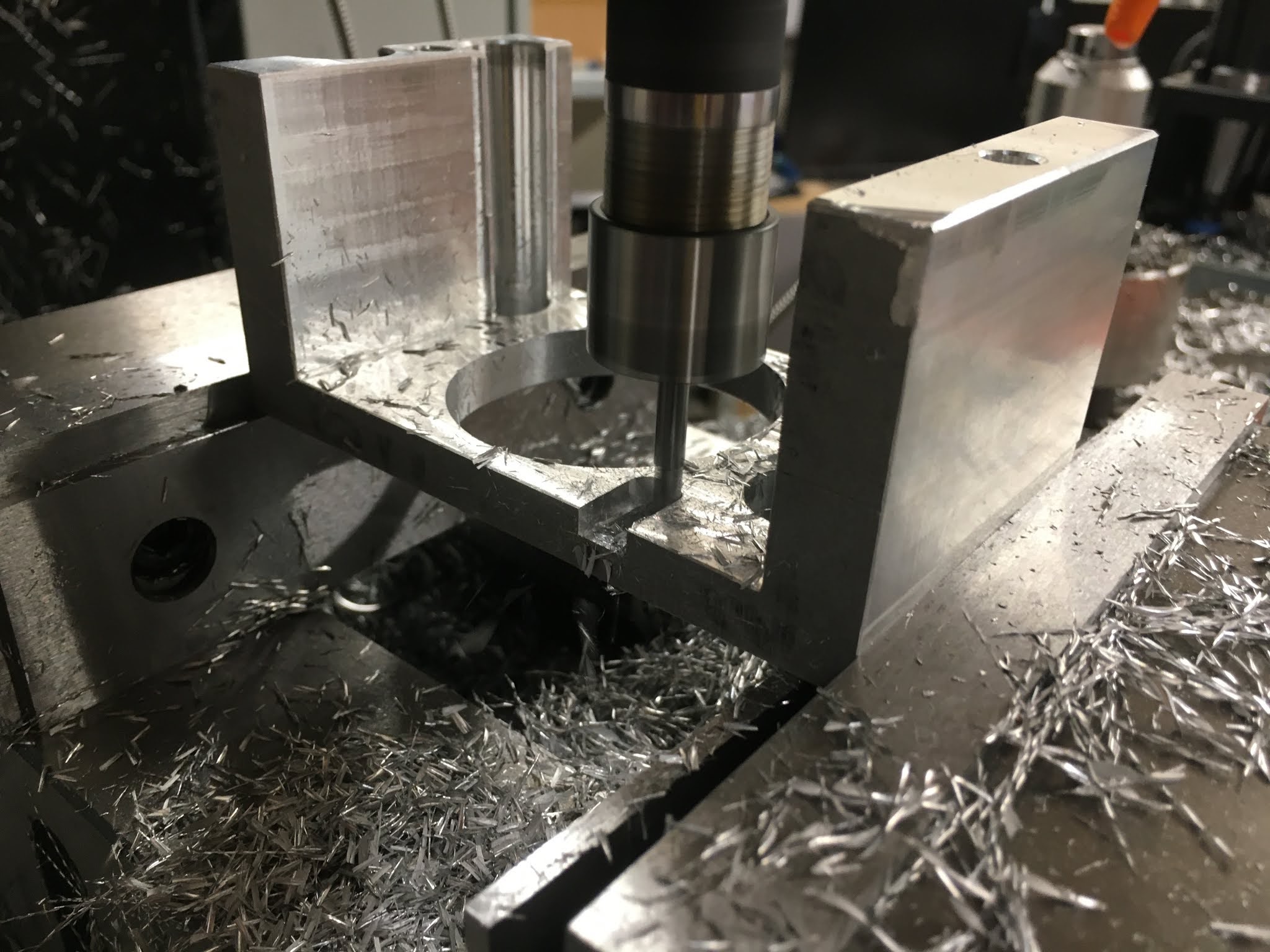
Flip the part:
Now, save that as an STL file, import it into the design space, convert it to a solid and then sue that for the stock for the next (bottom side / "rear") setup.
I managed some heroic MRR and a pretty impressive spindle load. I didn't measure it (I could have displayed that on the VFD digital operator panel) but it was sounding as if it was working for its supper.
Ping time?
And again, I was caught out by swarf getting recut and melting onto the tool. PING!! It's good to have a bit of fun. Although it was far from new, a replacement cutter like this from APT is around £20 but it feels worth it in the interests of science.
Once it stops cutting, the machine is trying to plough the tool through solid metal. This doesn't usually work out well for the cutter.
As ever, the welded chips are plain to see:
Slight misalignment between top and bottom but it's not critical which I suppose is why I didn't spend ages setting it up.
Open up the motor slot: I didn't CAM up the slots for the fixing nuts. Nor did I open up the slot for the motor itself. It's a 50mm register and I simply created the feature from the motor model by projecting the motor geometry onto a new sketch. That's nice and simple but provides no clearance between the motor and the bracket. And if the parts aren't bang on or oversize, the problem is even worse.
The solution is to repeat the 2D Contour operation, this time with "radial stock to leave" set to a negative value. In this case I made it 0.2mm, allowing a nominal 0.4mm of total slop, which is fine for the application:
This worked nicely and didn't require a second visit, although picking up the part origin was a bit tricky. I chose the centre of the front cylindrical surface and the top of the internal surface. The Renishaw probe was just long enough to do this without fouling:
Machine the fixing slots:
Next, the 4mm single flute end mill had to be set up in an extension so it could reach the workpiece without fouling the sides. This is a 20mm shank with a 22mm nut. I created a new tool (#36) for this:
The closest surface I need to machine is 9.663mm from the main vertical face of the part, so with a 22mm nut and 4mm tool, I have just a nominal 0.66mm clearance. That should work - just.
Set up the tool length:
And get cutting - 6000rpm and a mere 0.02mm per rev feed. As I didn't use Tim Paterson's add-in, the rapids were limited to the max feed rate, so this took effing ages. That was the only mistake I made and I couldn't be arsed to go back and reprocess the op.
Seems to be largely sensible:
This is where it could get interesting:
Yes, you could just about get a gnat's cock in there.
Finished Job done, though. I'm not bothered about finish machining the (non-functional) underside. The adaptive toolpath pattern is fine.
The nuts fit the slot nicely, as does the motor itself, with its 10mm of movement.
Good. Next - machine the mating part with suitable M6 holes for the fixings for this bracket. Then I will have the whole cross slide assembly done. The back-to-back angular thrust bearings arrived, so I can fit those when I come to reassembly of these parts.


No comments:
Post a Comment