Retrofitting 1983 Shizuoka AN-SB CNC milling machine, Bridgeport mill, Colchester Bantam lathe and 1982 Tree UP-1000 CNC lathe with modern controls - and other workshop stuff
I need to model up a few tools and toolholders for my machine. It's perfectly possible to use the generic tools and holders from the installed library but if you do that, the tool and holder dimensions won't be right. That prevents the simulation from identifying tool collisions and may also allow the toolpath generator to attempt to use a part of the tool that isn't intended to cut. The tool library in Fusion allows you to make your own components. First thing to model up is a few toolholders. Every one seems to have its own gauge length (from the reference face on the nose of the spindle to the end of the holder) and the various holders have all manner of diameters and features. The other issue is that none of the examples are ISO40 like mine.
On my first attempt, it was helpful for me to play with and edit something to start with. And now that I've made up a few ISO40 toolholders I can modify them as required.
My first holders are for face mill, end mill and ER40 collets. Here's the end mill holder. You can see that the editor is pretty straightforward to use. It's generating a series of cylindrical or conical elements defined simply by start and finish diameters and a length. You can add and remove section as required. Here's the end mill holder:
ER40 collet holder:
Having made up a few holders, I then took the next step ie added cutters. For the face mill holder I only have one face mill, so this was fairly quick. Here's where the combined holder and face mill is defined:
Here's what it looks like in the library:
For the end mill, I added the Mitsubishi BP300 indexable tool I've already tried out on the machine.
And finally, I have the ER40 collet chuck with a 3/4" hogging end mill for aluminium.
The end result is a tool holder and tool within the CAM environment. This is the face mill and tool path:
Here's where a collision is detected between the tool shank and the workpiece. Along the bottom of the screen is a timeline showing all of the collisions. Basically the BP300 cutter isn't long enough to reach down into the cavity. Changing to a long cutter avoids that problem.
Although the Newker CNC controller is (apparently) very closely based on the Fanuc M series controllers, obviously there are some areas where functions, g-codes etc differ. The post processor (PP) in Fusion 360 to select for the Newker controller seems to be the generic Fanuc milling one and so far (very early days), it seems to be compatible. Having said that, it's clear that some of the setup parameters will need to be modified for the Newker / Shiz combination. I'm still in the very early days of CNC and this is my very first attempt at getting a machine up and running. I'd already tried to decide if I should be aiming to get the machine to move to some sort of home position after program end - and if so, what to do about it. It seems that some machines have a "machine home position" that lifts the spindle to top position, then centres and brings the table towards the operator so the vise and workpiece are easy to reach. There seem to be several ways to do it.
The G28 and G30 commands are supposed to take the tool to the home position (in absolute machine coordinates) via an intermediate (safe) point. Not all machine controllers support this. Furthermore, from what I can tell, you can't specify a position relative to the home position, only the home position itself. It's unlikely to be quite where you want it.
G53 is a non-modal command and also references the absolute machine coordinates. So regardless of where you are and what coordinate system you are currently using, issuing a G53 command with specified coordinates will take the tool there. That sounds like a suitable plan.
The generic Fanuc PP does a G28 at the end of the file, so I was manually editing it out on my trials, to avoid the machine disappearing off to the home position at the end of the job. Home position is a long way away from the machine vise on the Shiz.
The PP used in Fusion 360 is closely based on the HSMWorks PP. It's written in Javascript which I've never used before. I'm too old for all the thousands of versions of code these days. Most look similar enough to the stuff I've used in the past to look intelligible at first glance but are different enough to be almost impossible to do anything with in practice.
In terms of the homing issue referred to above, there is also a rather handy Youtube video from At-Man Unlimited (Tim Dykes) that shows how to configure your PP to enable or disable G53 homing.
Seems that Pootube robots prevent him from posting the code changes on their site (go figure) but he emailed me them instead:
At-Man recommends Notepad++ for these edits. It's pretty good for editing software code and you can tell it you are working in Javascript so it applies appropriate assistance.
Firstly, insert these lines into "user-defined properties":
// user-defined properties
properties = {
SetHomePosition: true, //enables set home position
HomeX: 1, //set x home position
HomeY: 3, //set y home position
useFilesForSubprograms: true, // specifies that one file should be generated to section
writeMachine: true, // write machine
etc etc
Then within the onOpen function, add these:
function onOpen() {
if (properties.useRadius) {
maximumCircularSweep = toRad(90); // avoid potential center calculation errors for CNC
machineConfiguration = new MachineConfiguration(aAxis, cAxis);
setMachineConfiguration(machineConfiguration);
optimizeMachineAngles2(0); // TCP mode
}
if (properties.SetHomePosition) {
machineConfiguration.setHomePositionX(HomeX);
machineConfiguration.setHomePositionY(HomeY);
}
The result of this is a couple of options in the post processor popup:
Enabling "SetHomePosition" generates the G53 command with the X and Y coordinates also specified there. Disabling it reverts to the default G28. The current X and Y values are just placeholders for now. As my machine is metric, they wouldn't result in much movement from the machine home position.
I will try out the effect of this on my machine ie see if it actually does what I want. And if so, figure out some sensible values for the X and Y coordinates.
3 years ago I became frustrated with the ball ache involved in changing toolholders on my then new-to-me Bridgeport clone milling machine. I was also learning about CAD and decided to design a quick change toolholder system for it. There didn't seem to be anything suitable on the market to buy or copy, so I measured up the key components and set to. I posted about the saga on the Model Engineer website, so no need to go into detail here. I picked up a few more toolholders over the next year or two, almost entirely from ebay in the end. Although the numbering systems used is fairly confusing, I soon learned that there are several sorts of toolholder based on the 30 size taper:
ISO30 / INT30 / NT30 with parallel shank and a metric (M12) thread
NMTB 30 with parallel shank and an imperial thread (1/2-13 in USA, probably 1/2" BSW in UK)
BT30 with no parallel shank (intended for pull studs)
Possibly various "shankless" close relatives to the BT30 (SK30?? etc).
In my case, the original drawbar was metric, so perhaps the system that came with my machine was technically ISO30, not NMTB30. However, it only came down to the thread on the drawbar. This was probably imported from China or Taiwan into Canada, so not surprising that it has quite a few metric threads on it.
With the new quick change system in place, it seemed I could use either of the NMTB or ISO shank tools. However, it finally dawned on me that BT30 tooling could also be used just as easily if I simply fitted a longer pullstud. And given that the pullstud is to my own design , I'd have to make or procure them myself. BT30 tooling sees to be more widely available and less expensive, although it still works out costing more than 40 taper tooling despite its smaller size and reduced material cost. This is almost certainly due to BT30 being used on more modern / industrial machines than the old shanked tooling.
The missing part required to convert ISO30, BT30 etc tooling to make it suitable for my quick change system is the pullstud. Although it's a fairly simple design, I'm really not set up for making runs of 20-40 pullstuds, either temperamentally or in terms of my workshop facilities, so I looked at getting them made by a supplier. There seem to be many workshops offering to undertake small runs of CNC components.
I drew up both versions of the pullstud in Onshape. This was emerging as an exciting new product with the potential to be a cost-effective solution for hobby users. I was involved in the beta testing of the early product and found it to be reasonably easy to use. The main downside was the limited storage available for free and the eye watering cost of the various add-ons, such as the 3rd party CAM apps. Fusion 360 came along not long afterwards and must have put a pretty big hole in their business model. Either way, it wasn't long before I made my excuses and left for Fusion 360. This is the "long" version of the pullstud:
On a visit to my employer's factory in China, I enquired about having some made at one of their suppliers. This was what happened in the end. I provided them with drawings for both the long and short pulls stud and on my next visit, I received 20 of each part. Note the yellow highlighted dimension (18mm diameter) - more on this later....
Onto today (actually yesterday now), and I've been looking at the lathe and manual milling machine recently and feeling guilty at the way they've been neglected during the recent move from Canada and the workshop build. I've needed to use them for small jobs and it seemed a good time to do something about them.
Seemed like a good time to dig out the various tooling I've acquired over the last 3 years and unite them with these fancy new pullstuds. For one thing, it would be helpful to know that they actually work. Back then I did some careful measurements to try to ensure that the long pullstuds would simply screw in and work. It wasn't possible to achieve that with the short pullstuds, as the standard shank is too long to coexist with my collet system, so some machining back of the NMTB / ISO shank was always going to be necessary. Which was another reason for preferring the BT30 tooling in the first place.....
Bugger. The highlighted 18mm diameter wasn't right. I don't recall the exact circumstances but I either guessed the dimension, read it incorrectly from the model or typed it in incorrectly. Either way, it should be 16.5mm and it says 18mm on the drawing. The stud simply won't fit up there if it's too big.
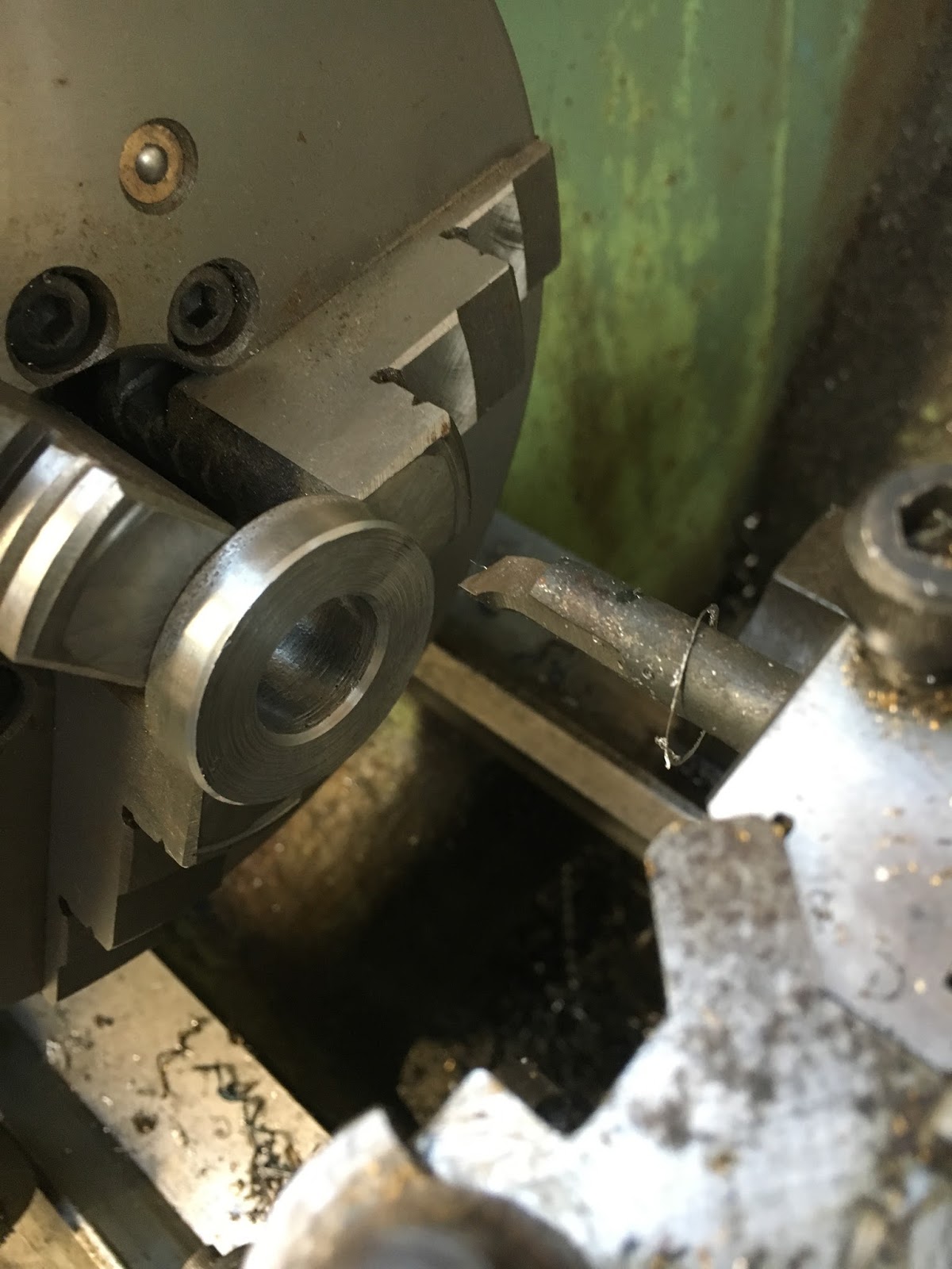
These are made of 1045 carbon steel, through hardened to HRC 56-60, so machining is possible but not entirely conventional. Using carbide tooling and with the lathe at maximum speed (1600rpm), it's simple enough to machine hardened steel. The material is melted as it comes off due to the high cutting speeds - if you can get the surface speed high enough. First - make up a threaded adaptor to hold the pullstud for machining:
Turned down and drilled out, now tap M12:
Finished and ready to go:
Sorry about the way I was dancing about at the end here. Those bits of burning swarf hurt like hell when they land on your arm.
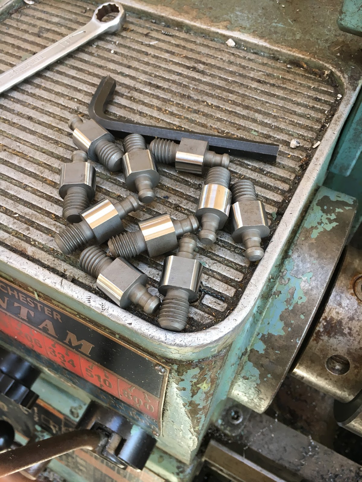
I machined 10 of each of the studs by setting up the carriage stop (to stop the tool a fixed distance away from the chuck) and cross slide stop (for diameter). Job done:
The machine ends up covered in a sort of funny bum fluff:
Here are a few ISO30 and BT30 tools with their new pullstuds fitted. The drill chuck has one of the original hand made pullstuds. Below are a BT30 (middle) and ISO30 (bottom) :
Here's another BT30 tool:
And the proof of the pudding:
I'll use Loctite to bond them in, now that they appear to be a success. Good result!
The Colchester Bantam didn't come out of its storage / exposure in best condition after its time under canvas while the garage was being constructed. I had to move the machines during the Winter for various reasons, even though the garage was little more than a concrete pad at the time. Despite being covered by large tarpaulins, I knew they would suffer some surface rusting. I coated some of the surfaces with WD40 etc but it was never going to be pretty.
Both the Bantam and the Bridgeport clone look pretty nasty but I'm reasonably happy that I can recover most of the damage. My preferred technique is to use a vibratory sander with a green pot scrubbing pad - these pads engage with the "hook and loop" base on the machine. I have a cheap and nasty one for this purpose and keep the better machines (Makita etc) for clean work. When lubricated with WD40, the rust comes off fairly quickly and wipes down with industrial tissue. And being fairly benign, the actual base metal is hardly touched by the pot scrubbers. That's the theory anyway. Besides, my machines are hardly in pristine condition.
It's pretty quick and easy to remove the cross slide by simply winding it out to the back and then lifting it off. And the top slide unbolts by removing 2 bolts. This approach makes it much easier to clean off the flat surfaces and clean out loads of swarf and crud at the same time. Most of the other painted(?) surfaces clean up with WD40 and tissue.
This is what the cleaned up machine looks like - somewhat improved:
I also have a Multifix clone toolpost to fit to the topslide. I bought this from Create Tools in China at a fraction of the price of the Swiss original, yet it seems to be well made and certainly good enough for the likes of me. For the Bantam, the "A" size is the best fit. Naturally it's not supplied as a drop-in replacement for the Dickson system, so some work is required. The bush st the top of the hold-down bolt is soft and can be machined out (drilled) to 16mm to clear the 5/8" stud. I did that on the Blidgeport, using an edge finder and the DRO to locate the centre of the hole accurately. You can see the state of the table in these pictures - I'll sort that out later....
That leaves the location bush at the bottom of the stud. This locates the bore of the toolholder body into the cross slide body. I'll need to reassemble the machine before I can turn down the original bush to the required 20mm OD.
You can see how the stud assembly is held in a large tee slot in the top slide and located there by the location bush. The large diameter register that pokes out the top fits into the bottom of the Dickson body (the funny castellated thing at top right) but is too big for the new Multifix body (the splined cylindrical thing sitting on the topslide).
I need to machine a location bush to fit in the 20mm bore of the Multifix body, leaving a sort of top hat shape. Found a suitable piece of steel, clocked it up in the 4-jaw and turned it up, drilled it out and parted it off. Or I would have parted it off if the insert hadn't jammed in the slot. I don't have any coolant and wasn't feeding any WD40 on it, which might not have helped. Used the hacksaw and then faced it off instead.
It started out nicely enough....
When the parting tool jammed, the work slipped in the 4-jaw. Gives some idea of how hard they can get stuck.
The register ended up almost exactly 20mm, so was an excellent fit in the Multifix body. I find that I can use the micrometer dials on the cross slide and get a very precise and consistent diameter. That's handy, as carbide tooling prefers to take a decent cut, like a couple of mm at once, so if you play your dials right, you can pretty much end up bang on target in one decent final pass.
I finished by chamfering both the bore and the outer edge of the location feature with a boring bar. To avoid having to change the angle of the tool after chamfering the bore, I simply move the tool behind the centre line and turn the spindle in reverse to chamfer the outer edge.
The end result - a tap fit into the top slide and a tight sliding fit into the Multifix body. One of my better efforts, then:
So that's that then. I'll have to set up all my lathe tools in the new holders of course. The final plan is to replace the topslide with a solid block. That way you lose the ability to do things like chamfering by feeding the tool at an angle, or feeding a threading tool at 29 degrees etc. But on the other hand you gain in rigidity (for operations such as parting off, where insufficient rigidity can result in....the tool jamming). For that approach I will need to make a large-ish block that locates on the central spigot and is held down either by the existing fixings or by some new ones. I don't mind butchering my machines by taping extra holes but there again, the Bantam cross slide is peppered with all manner of holes as standard. These are for things like rear toolposts and the gib adjusters but certainly a few extra won't do any harm. Anyway, that will have to wait for now.....
Finally got round to opening an account with BOC on Wednesday. If you want to make use of the Volkzone offer (Y size cylinder at a low rental for hobby users), you can't do it at a BOC agency or over the phone. However, the Docusign form from Stu Anderson (bus dev mgr) was quick and easy. The credit check(!) was completed this morning and I got my account number. So I called in at CPK Welding on the way home this afternoon and picked up my first cylinder of Pureshield. That's 100% argon for TIG welding. For MIG welding steels you generally have some CO2 added. Technically this should be referred to as "MAG" welding (Metal Active Gas), as the CO2 is not inert during the welding process. Hardly anyone uses the Y size cylinder these days, which is presumably why BOC have come up with the Volkzone offer. Better to have them lying about gathering dust in hobby workshops earning rental for BOC than sitting unused at the BOC depot gathering dust! I really don't need to connect up the gear selection solenoid yet, as I will be doing mostly high speed work, so for now I just need the power drawbar engagement solenoid to be connected up. This brings the electric impact driver down onto the splined (top) end of the drawbar. It shouldn't require much pressure, as it only has to work with the weight of the impact driver to overcome the return spring. My cunning plan was to use the argon cylinder to operate the pneumatic solenoid instead of using compressed air. I need argon anyway at some point soon, so it's possibly a cheaper solution for now, until I can get my hands on a small, quiet, used compressor. Connected up the solenoid ("air" line and electricity), then ran a line to the back of the machine. At this point I had to swap over the brass fittings on the argon regulator. When I took my stuff to Canada in 2010, I found that the regulators didn't fit the N American gas bottles. However, I was able to buy the appropriate brass nuts and swap them over. The tricky bit was figuring out if the stub poking out of the regulator had right or left hand threads. None of the thread was visible, so it was a question of trial and error at the time. At least I remembered today that they are left hand threaded. iCloud Photos app for Windows is infuriating. How they can have come up with something so counterintuitive and downright inconsistent is hard to comprehend. Anyway, out of the 15 or so photos I took this afternoon, 4 of them simply refuse to be downloaded, including the regulator pics. Bloody Apple. I'd love to meet the knobs who were (are?) responsible for this, just to understand what makes people behave like that. Are they arrogant, stupid, ignorant, deliberately obstructive - or all of the above? If you've used iCloud Photos you will know what I mean. I used the dual dial regulator that I normally use with the TIG welder. The first gauge indicates the pressure in the cylinder and as argon does not liquify under pressure, that is a handy indication of how much is left - it reads 230 bar when freshly filled. The second gauge is supposed to indicate the gas flow rate, although with no gas flowing it seems to indicate pressure, so as you wind the regulator knob in and out, the needle goes up and down. I also half inched the first few inches of the MIG gas hose and spliced it onto the end of the 1/4" Nylon hose. Job done, now to try it out. I set the regulator to a fairly low setting. I haven't bothered trying to measure what the actual pressure is but it works fine, so little point increasing it any further.
Heheh, that's better! Now on with the curtains: 3mm neoprene is pretty heavy stuff when you have to hang a 80cm wide piece of 1.4m sheet in 3mm thickness. But it's done. Forgive the Brown Stuff in the workshop - it is holding the top of the sheet up and gives another 20-25cm of height.
The slideway cover on the front of the saddle is clearly not a "genuine" replacement and is too long so that it hangs over the front of the chip tray. Any coolant and/or swarf will end up on the floor, so it seemed a good time to shorten it and anchor the front end. Fitted a piece of loominum angle section using 2 of the bolts that secure the cover on the Y axis drive belt, then fixed the front of the cover with M4 stainless button headed screws.
The slideways are chrome plated and seem to be in good nick. I think generally, one of the (cast iron) surfaces is chromed and the mating surface is scraped and unplated.
This the curtain work completed:
Finally, time to get round to refitting the machine guard, as much for swarf control as personal safety. This is a Nelsa system. Seems they still sell it - or something very similar. It's called the "slide and swing aside" (SSA) system. It's in reasonable condition, considering. The main downside of this (not having actually used it yet, mind), is that it limits how high you can raise the knee before the top of the guard hits the bottom of the head / console / support arm. If I find that I have to use the quill near full extension, I may refit the machine vise on its swivel base to raise it up an inch or two. As it was, I moved the vise 2 slots closer to the rear of the table so that the tightening screw clears the sliding door.
So that's it - power drawbar operational, curtains fitted and machine guard refitted. Bargain buckets.
Where's the backlash then? Yesterday I took the Z axis ballnuts apart to see if there was any means of adjusting out backlash in the ballscrew assembly. Indeed there is, although there was barely any backlash take up when I tightened them together with the locking strips removed. So clearly the backlash was elsewhere. I reassembled the ballnut / yoke assembly - nothing to be done in there. I'm no metrologist and that's not by accident - it's not my favourite activity. However, I have the basic equipment that will at least give an indication what the source of the backlash is. I have 2 DTIs - one is a Kurt-branded Chinese thing with 1" of travel and 0.001" graduations (being Mercan, it's imperial) and a Swiss "Baty" brand with 10um graduations and 0.8mm total travel. 0.001" is about 25um, so the Baty has slightly higher resolution - but not by much. I should get a better one. With the DTI clocking axial movement right next to the ball nut, there is no discernible movement of the needle as the ballscrew is turned. That agrees with the tiny backlash seen when the ballnuts were removed. Despite what I said yesterday, the most likely explanation is the slop between the quill and its bore in the head. And sure enough, when I measure the axial backlash at the quill end of the ballnut yoke, it is measurable. So the quill is not moving in a simple axial direction. This machine had 20 years of (careful) use.
Furthermore, when radial backlash is measured at the nose of the quill, I can see the best part of 40-50um. Note that I'm doing this with the quill near full extension. And when I draw the quill right back to top position and measure the radial backlash, it is almost immeasurably small.
The way I measured the radial backlash was by driving the quill down onto a large, hard rubber mallet. This loads the ballnut, resulting in a torque on the quill and taking up any radial backlash. The rate of wear of the quill and also the radial backlash at the quill nose will be significantly higher the further out the quill sticks. And sure enough, as noted above the measurements appear to confirm this, even though they are very basic. The lesson is fairly obvious and hardly a revelation - minimise the quill stick out at all times, particularly when accuracy is required. It's curtains for the old beast! I took delivery of my 3mm thick black neoprene sheet today: 1.4m wide and 3m long. So I dug out the frame that the original curtains were suspended from. The 3 sections are held together in line with M4 screws. The centre section bolts to the machine body. Then the rubber curtains are fastened to the side sections by the 2 thin strips. There is already a slideway cover behind the table which will be left in place.
Also refitted the giant chip tray - as well as the optional power drawbar, this machine came with the optional chip tray and presumably the curtains were part of that system. Just a pity it didn't get the automatic tool changer too.... Given the rather fetching stream of swarf I managed to generate on my first metal cutting trials, the chips aren't simply going to fall on the table and need sweeping up. I need to catch them, to prevent them streaming all over the shop. This is the original position for the rails:
I took the chance to reposition the top of the curtain slightly higher, right up against the bottom of the ram assembly. The neoprene is wide enough for this. It simply required a couple of new M6 tapped holes and a hole in the existing rear slideway cover for the coolant hose.
Job done and it looks good. Next job will be cutting and fitting said neoprene curtains.....