Tuesday, 15 May 2018

Centroid Acorn software update 4.12 - and refrigging the parameters

Software update 4.12:

Finally, Centroid released the long awaited update to 4.12 (from 4.10). This implements a few features and fixes:

  • Wireless USB (I already have one waiting).
  • Probing functions that actually work with the paid-for "digitising" option. They forgot to enable it in release 4.10(!).
  • Rigid tapping (I had to disable it to get the "digitising" features working in the beta 4.11. So I had it working but was unable to use it).
  • And a host of fairly minor changes.
In "detail", this is what was declared:

Acorn CNC12 v4.12 release notes
1.) Wireless MPG support for Centroid XHC model CWP-4.
2.) Contour ShuttleXpress support.
3.) added “Limit All” and “Home All” functionality to Wizard (use one input for all home switches and another for all limit switches, OR use just one input for both all home and all limit switches, saves inputs)
4.) added Wizard “control peripherals” tab added and those related items have been moved out of the spindle tab into the accessories tab.
5.) Default step frequency for AC drive types now defaults to 400 kHz
6.) Automatic Tool measurement in Mill and Lathe Pro now activated for all tool numbers
7.) Extended WCS (7-18) activated in Lathe Pro for a total of 18 WCS positions
8.) Rigid Tapping selection in wizard automatically sets all Rigid Tapping parameters to match the Tech Bulletin
#304 (Acorn - Rigid Tapping Setup for Mill and Lathe), and allows users to edit those values in the Wizard
9.) Added Tool Touch off auto configuration to Mill Wizard
10.) Changed default steps/rev in “bench test” from 200 to 1600
11.) When importing a license file, an error message is displayed if the serial number extracted from the license file does not match the system serial number.
13.) Support for the new Centroid CWP-4 wireless pendant is included with Mill Pro or Lathe Pro CNC12 License (or Mill Dig bundle) a Pro license is required for use with the new wireless MPG. (Note: Wireless MPG pendant support is not included in the Free version of CNC12, however Contour ShuttleXpress support IS included in the Free version of CNC12)
14.) Changed VCP to always clear Rest Bit and Set ResetOk on shutdown
15.) Added to the Wizard the ability to control the default VCP jog mode on start up of CNC12.
16.) Refreshed and Updated Acorn_rev3 schematic set found here.
16.) Misc:
- Wizard UI improvements/changes
- Wizard now starts in top left of screen to insure user can move/re-size window
- Wizard “force on top of desktop” has been removed.
- Changed Acorn power off and reset message to "Please power cycle Acorn and then restart CNC12, Press any key to exit".
- Added aux10, 11, and 12 LED's to VCP
- Mill/Lathe Pro License rigid tapping bug fixed
- CNC12 can only be installed on the CNCPC C:\ drive, selection for other locations has been removed.
- Reordered Max, Fast and Slow Jog rates in the Wizard for better flow.
- fixed worklight bug not being mapped to aux key
- added notes to Acorn specific CNC12 parameters in the CNC12 configuration menu
- Wizard: Added Keyboard navigation by tab and enter. Textboxes will now highlight on click also.
- Wizard: Improved error message handling for max/fast/slow rates in relation to the wireless mpg.
- Wizard: Fixed max rate/fast jog value check error message bug.


Operation of TT and Probe:

Obviously I was expecting my TT and probe changes to have become invalidated and sure enough I was right. They'd made some changes to the config wizard with a view to setting up tool touch (TT) setting. But they have never managed to convince themselves there was a problem trying to run both a TT and a Renishaw-type probe, so why would they bother testing them out, least of all get them running? And sure enough, it's clear that they didn't.

Took me about an hour to sus out the parameter changes. Basically they'd inverted 2 of the parameters for some inexplicable reason. The "software release notes" are nothing of the sort and simply summarise some of the changes without going into any details. I suppose you might argue that some of the details may be commercially sensitive but even so....

Parameter and input settings required for operation with 4.12:

Here's my summary, as posted on the forum.

There have been some changes to the setup required to run TT and probe simultaneously under the 4.12 update. Took me an hour or so of experimentation to find the correct parameter settings, as the "release notes" don't actually tell you what has changed, only that there have been some changes (grrr!). Bottom line - here's the setup that seems to work with 4.12 on my machine:

Inputs and settings:
* Renishaw probe trigger goes to input 4. Described as "Unused" and "NC" in the wizard. It's normally closed, so contact opens the switch and the input is pulled up to 24V.
* Renishaw probe detect goes to input 6. Described as "ProbeDetect" and "NC" in the wizard. It's a simple loop to ground inside the plug.
* TT trigger signal goes to input 7. Described as "ProbeTripped" and "NO" in the wizard. My probe is also a normally closed electrical switch, so contact with the tool lets the input signal go up to 24V.

Parameter settings:
* # 11 is "-4" (TT to input 4, the sign indicates the type of input, NC or NO)
* # 12 is "10" (the tool number of the Renishaw probe in the library)
* # 17 is "3" on my machine (represents "G30 P3" command). The P3 coords are stored in the WCS table / return table. The coordinates define the position of my (fixed) TT. It rapids there before doing tool measurement with the TT.
* # 18 IS NOW "-6" (changed in 4.12). The input that is checked to see if a probe is connected. If so, the spindle is inhibited.) NB: You should also set #257.
* # 257 is "+6". Yes, NOW POSITIVE six (changed in 4.12). "Tool touchoff detect". Parameter #18 requires this test for the Renishaw probe but you have to fool it for the TT probe.
* #43 is 2 ("use #44 defined input for TT")
* #44 is 7 (TT input channel number)

This gives me auto tool length measurement (using my Chinese TT) AND plug in Renishaw probe (with "missing probe" detection) working.

Glad to say it's all working. 
  • My TT is hard wired. This was the only way to get it to co-exist with the Renishaw probe.
  • The Renishaw probe tool plugs in when required (handy, given that it's on an ISO40 holder). 
  • The "probe detect" feature prevents attempting to probe with the Renishaw probe without the it actually plugged in.
  • NB: Running the wizard again at this point would overwrite these settings - DON'T DO IT!! They have to be manually set by going in through the main menu (Settings > Config > Parameters etc).

Monday, 14 May 2018

Stronger overarm!

As noted yesterday, the "pin" supporting the overarm was a bit on the weak side. I'm limited to 20mm  dia if I am to make use of the Chinesium bearings. Really, I need to support the top of the pin. So time to have another go at the job.....

Chop off a couple of lengths of asymmetrical angle iron:


Turn down the pin to get rid of the shoulder. And reduce the threaded end to 16mm :


16mm hole in a 4" length of 4" x 1/2" bar to take the threaded end:


A length of 3" strip for the top - needs a 20mm hole so I can insert the new pin. Start with a pilot hole...


...bore out to 20mm clearance:


So it fits the pin. Here's the "cage" made from the 4"x4" plate and the strip:


Need to weld it up. As you can see, the pin drops in from the top, then is held onto the ram by the M12 bolt.


Sorted


The pin drops in through the bearings and the shoulder at the base of the pin locates on the floor of the box. Then the M12 bolt goes in from below the eye in the ram and holds it all together. I can report that it supported over 100kg of lard.....


Then with the help of a male offspring, I managed to get the damned thing onto the end of the arm. Getting it up into position is tough enough but you can't see and manipulate the pivot bolts without 3 or 4 hands and 4 eyes.


And there we have it. Although the motor encoder cables are not connected up, at least the controller still fires up - I haven't stuck a spanner through the display or ripped off the e-stop switch. Now that it's safely ensconced, I can get on with connecting up the peripherals....


Sunday, 13 May 2018

Finishing a few things off on the cabinet - and an overarm for mounting to the machine

A few details to finish off:

Having overlooked (forgotten) to fit a means of drawing air into the cabinet, I finally got round to chain drilling a 110mm hole for one. Of course, I don't have a mesh cover / filter either but I can fit that later. There's an exit grating above the VD but obviously without an inlet, not much will happen in terms of air movement.


I got myself a cheap (£10) room thermostat that can go up to 30C or so. That way, the fan will only come on when the internal ambient requires it. Being a "voltage free" device, it is purely mechanical in operation (a bimetallic disk), so dead easy to fit and use.


Also made up a male-female extension cable for the MPG pendant, with one end mounted on the front panel. It has a 15 way D connector at each end. This way I can plug the MPG in the front panel. Another PITA operation, requiring chain drilling and a fair bit of manual filing.


And on the D connector front, I had to refit the encoder connectors so that they are fitted from the outside of the cabinet. Otherwise the mating plug ends up being about 2mm from fully mated due to the thickness of the cabinet. Now the mating connectors fit correctly.

The motor phase connections come from DMM Tech with a 6 way inline connector. It looks like a Chinese copy of the Molex Mate And Lock series. I don't want anything like that close to the motor where there is likely to be swarf and coolant. So I cut and spliced the motor and extension cables together using adhesive lined heatshrink. Ideally I'd also do that with the encoder cables. Currently they are fitted with 9 way D connectors and the extension cable is a simple computer grade thing. Can't be arsed at the moment - I may attack this at some point later on.


Overarm for mounting the cabinet on the machine:

Before I get too carried away, there is some fabrication to be done. Some form of overarm and mounting framework is required to hold the controller / panel / display in position.

Rightly or wrongly I've gone for a large pin, mounted in the hole at the rear of the ram that is provided as a means of mounting the slotting head accessory. It's a machined 22mm dia hole. 


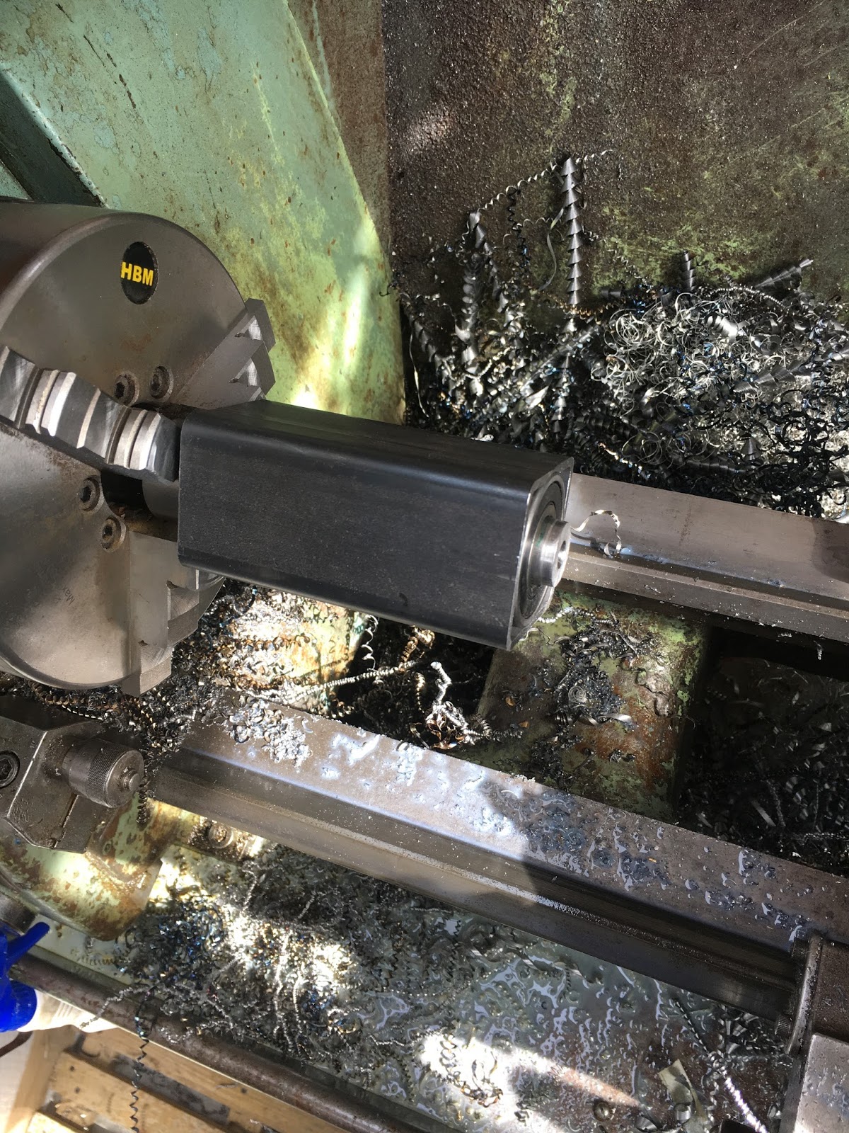
This thick walled (3mm) square section is just the right size to fit a couple of Chinese bearings. I bought a box of 10 from ebay some time back. All it needs is a bit of boring out:


Nice fit:


This is the guts of the bearing assembly - 2 Chinesium bearings and a housing:


Also found a piece of 1 1/2" BMS that will become the pin. Nothing clever here - just line up the parts and mark them up directly. 


Turn down the main body to fit the 20mm bore of the bearings:


Got an imperial circlip set I bought in Canada. It contains a wide range of internal and external sizes and it even comes with a pair of circlip pliers.


There we go. Seems to be a good fit:


Groove for the circlip:


Looks OK:


Turned down the other end, drilled and tapped for an M12 bolt. Looks good, although I must say it looks a bit weedy:


Make up an arm by welding some more square section to the bearing housing:


Needs a bit of support:


There. Need to get rid of the DRO and these sockets:


Now need some form of framework at the end of the arm to receive the cabinet. And yes, I "tested" the arm to see if the pin was about to shear off. It seemed happy to withstand something like 50-60kg (calibrated hands) which should be fine for supporting the cabinet. I'd guessed the finished cabinet weighed about 30kg. Out with the postal scales - 28kg on the nose:


Some 1" square tube to make a simple framework:


Bolted in place with two M10 bolts:


Here's the overarm thing with its outer pivot bolts:


Nearly killed me getting that thing up there. Have to say I'm not completely convinced it's man enough - wobbles a fair bit. If the pin shears off, all sorts of shit will get damaged. May have to rethink the "pin" bit of the plan, possibly replace it with a double-ended affair giving more support. Anyway, I'm not going to take it down again tonight....


I'll see if it's still up there tomorrow and think how to proceed. I'm thinking some sort of beefy bracket on the top of the ram where the pin is would be more secure than the daft pin and not require the whole thing to be made from scratch again. I hate to admit to anything that might be considered a cockup but on the other hand I'd hate to have the whole chebanc come crashing down....

Thursday, 10 May 2018

The Newker controller lives again!

Right. It's 90% wired up now. The motors are just freestanding on the bench and I haven't got all of the limit / home switches wired up. But it should function to a fair degree now.....

Couple of minor issues:
  • The servos needed to be set up for position control in step / dir mode before they would both work here. Only one of them had been set up thus previously (by me). Then they both did the business. To do this, you connect up to the drive with the RS232 adaptor and use the tuning software to select the correct operation mode. I'll be needing to go back in there at some point to tune the PID parameters....
  • I'd forgotten that I needed the MPG pendant connected up. As the controller is currently configured, the pendant enable button needs to be pressed for the system to move anything. Once I remembered that, it was all go. I'll have to figure out how to disable the pendant and revert to the control panel by default.
  • Trying to run 3 Leadshine SMPS power supplies from a single 6A Type B MCB didn't work out so well. Even with a 10A Type B, it was tripping at turn-on. I've ordered a 10A Type C to cope with the turn-on inrush current. I could go with a 16A Type B but that doesn't seem like the sensible solution. With the 10A Type B, it usually trips on the first attempt but will succeed on the second. Clearly the DC bus caps are partially charged by then, reducing the inrush current below the trip level.
And here we are. Short video showing the 3 motors cutting virtual air. This was running one of the programs I'd loaded in the past, chosen randomly from those stored in the memory.


I have only one home switch fitted at present (on the Z axis). This seems to work as intended during the homing sequence. For the other 2 axes I couldn't be arsed to connect any switches up so instead I set ridiculous machine limits in the config, to keep them from interfering. 

Wednesday, 9 May 2018

More wiring - getting there / Omron proximity switches.....


Here's the control wiring for the VFD. I've used the same scheme I used on the original Shiz wiring, since that's the way the Newker controller is already set up. So I have Run CW (S1), Run CCW (S2) and 0-10V (A1) control voltage. I will use the relay output (MA, MC) to provide a "VFD fault" output that can connect in to the e-stop circuit:


The German IP65 terminal box needs to accept 3 of these Omron proximity switches. I'm not 100% certain they will behave well enough but for now, that's what I am going with. They will provide the Z +L, Z -L and Z0 (home) inputs. The Z Step (+), Z Step (-), Z Dir (+), Z Dir (-) and 36V PSU also come in through here. Yes, the Leadshine driver uses the differential drive signals. In contrast, the DMM-Tech servos drives only use single-ended drive signals, like the CNCdrive servos on the Shiz.

I can't squeeze 3 of these cables in through one of these glands, so will fit one per switch. And a 4th one for the Leadshine driver.


Marking out: 


Wires stripped, crimped and connected up:


The other end is connected up to the controller:


These are the connections (in pen, look closely):


This is the proximity switch. I ordered 20 of them from some Chinese ebay shop, where they presumably fell off the back of a lorry. There are 2 versions of them - NPN and PNP - and in fact I received a mixture of both. I need to check which ones to use. 


Here's where we are now. 

  • Mains wired up (isolator, MCBs, VFD, coolant relay, PSUs, controller etc).
  • DMM Tech servodrivers wired up (X and Y, including encoder inputs and PSUs).
  • VFD wired up (controls, AC power, brake resistor).
  • Z axis / head umbilical (terminal box) wired up.


Still to come:

  • X and Y limit switch wiring (from terminal block on chassis plate to controller).
  • Lash up motors for all 3 axes (to test them out).
  • Lash up limit and home switches.
....then do some commissioning. 

Omron proximity switch TL-Q5MC2:

These are pretty neat. The datasheet shows the various models and options available.

The TL-Q5MC2 is actually the NC (normally closed) version. I'm thinking this probably isn't the one I want. The NO version would be the TL-QMC1.


  • 3-wire, NPN.
  • 17mm square, with 5mm sensing distance.
  • Various notes about application, sensing distance etc etc:


Get those tube bender brackets finished!

Last time, I'd drilled and bored out the brackets for the bearing and ballnut. To complete these parts and approach the point of assembl...