Having overlooked (forgotten) to fit a means of drawing air into the cabinet, I finally got round to chain drilling a 110mm hole for one. Of course, I don't have a mesh cover / filter either but I can fit that later. There's an exit grating above the VD but obviously without an inlet, not much will happen in terms of air movement.

I got myself a cheap (£10) room thermostat that can go up to 30C or so. That way, the fan will only come on when the internal ambient requires it. Being a "voltage free" device, it is purely mechanical in operation (a bimetallic disk), so dead easy to fit and use.


Also made up a male-female extension cable for the MPG pendant, with one end mounted on the front panel. It has a 15 way D connector at each end. This way I can plug the MPG in the front panel. Another PITA operation, requiring chain drilling and a fair bit of manual filing.


And on the D connector front, I had to refit the encoder connectors so that they are fitted from the outside of the cabinet. Otherwise the mating plug ends up being about 2mm from fully mated due to the thickness of the cabinet. Now the mating connectors fit correctly.
The motor phase connections come from DMM Tech with a 6 way inline connector. It looks like a Chinese copy of the Molex Mate And Lock series. I don't want anything like that close to the motor where there is likely to be swarf and coolant. So I cut and spliced the motor and extension cables together using adhesive lined heatshrink. Ideally I'd also do that with the encoder cables. Currently they are fitted with 9 way D connectors and the extension cable is a simple computer grade thing. Can't be arsed at the moment - I may attack this at some point later on.


Overarm for mounting the cabinet on the machine:
Before I get too carried away, there is some fabrication to be done. Some form of overarm and mounting framework is required to hold the controller / panel / display in position.
Rightly or wrongly I've gone for a large pin, mounted in the hole at the rear of the ram that is provided as a means of mounting the slotting head accessory. It's a machined 22mm dia hole.

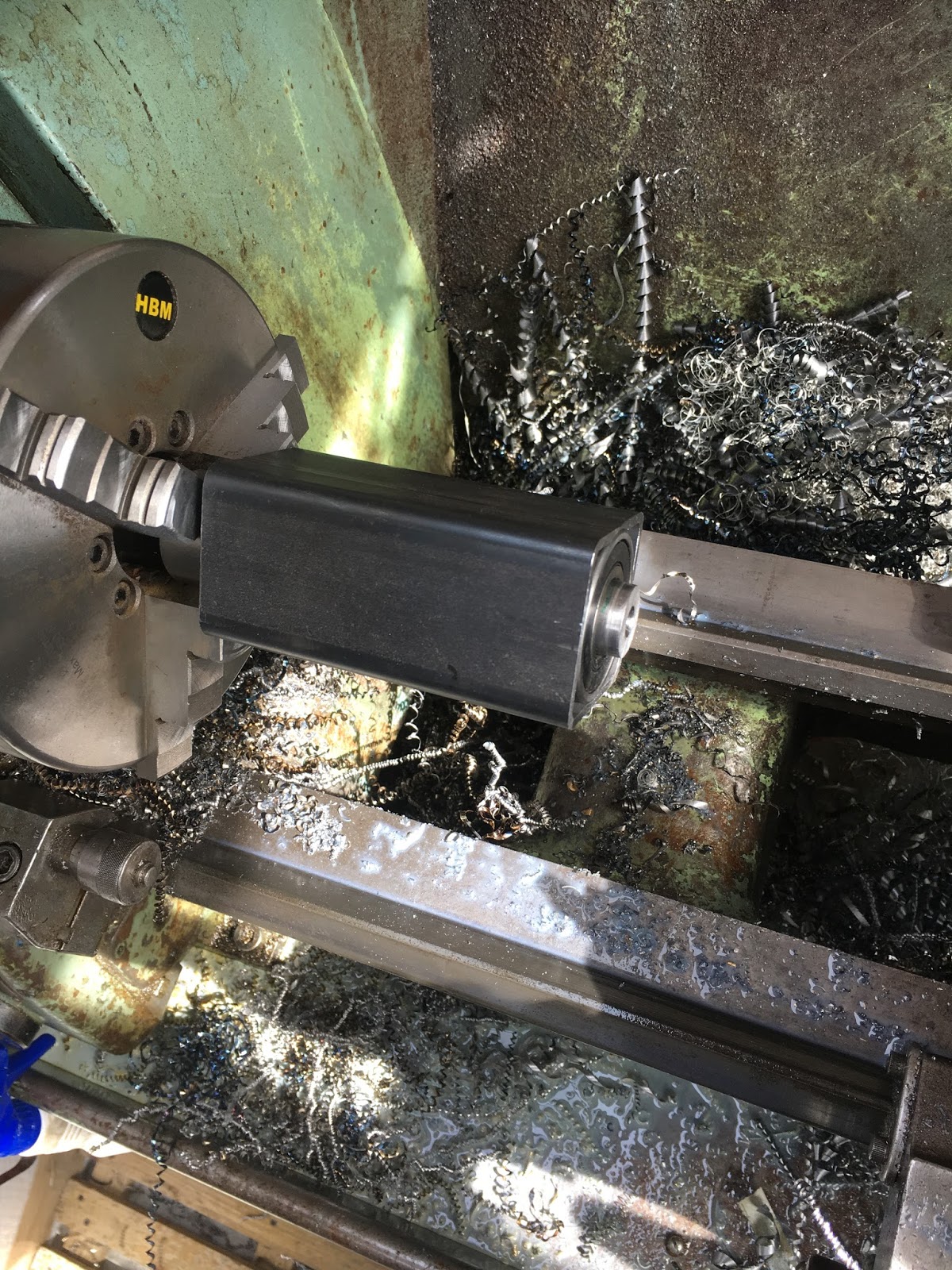
This thick walled (3mm) square section is just the right size to fit a couple of Chinese bearings. I bought a box of 10 from ebay some time back. All it needs is a bit of boring out:

Nice fit:


This is the guts of the bearing assembly - 2 Chinesium bearings and a housing:

Also found a piece of 1 1/2" BMS that will become the pin. Nothing clever here - just line up the parts and mark them up directly.

Turn down the main body to fit the 20mm bore of the bearings:

Got an imperial circlip set I bought in Canada. It contains a wide range of internal and external sizes and it even comes with a pair of circlip pliers.

There we go. Seems to be a good fit:
Groove for the circlip:

Looks OK:

Turned down the other end, drilled and tapped for an M12 bolt. Looks good, although I must say it looks a bit weedy:

Make up an arm by welding some more square section to the bearing housing:

Needs a bit of support:

There. Need to get rid of the DRO and these sockets:

Now need some form of framework at the end of the arm to receive the cabinet. And yes, I "tested" the arm to see if the pin was about to shear off. It seemed happy to withstand something like 50-60kg (calibrated hands) which should be fine for supporting the cabinet. I'd guessed the finished cabinet weighed about 30kg. Out with the postal scales - 28kg on the nose:


Some 1" square tube to make a simple framework:


Bolted in place with two M10 bolts:

Here's the overarm thing with its outer pivot bolts:

Nearly killed me getting that thing up there. Have to say I'm not completely convinced it's man enough - wobbles a fair bit. If the pin shears off, all sorts of shit will get damaged. May have to rethink the "pin" bit of the plan, possibly replace it with a double-ended affair giving more support. Anyway, I'm not going to take it down again tonight....

I'll see if it's still up there tomorrow and think how to proceed. I'm thinking some sort of beefy bracket on the top of the ram where the pin is would be more secure than the daft pin and not require the whole thing to be made from scratch again. I hate to admit to anything that might be considered a cockup but on the other hand I'd hate to have the whole chebanc come crashing down....


No comments:
Post a Comment