Got the stock cut down to roughly the right size (more on this later....) ie close-ish to the stock I modelled in Fusion. Manually drilled and tapped the holes in the stock and the fixture bracket on the Blidgeport, tapping the M10 holes with a machine tap (spiral flute) in the low speed range, using the VFD to reverse when the DRO indicated the tap was close to the bottom of the hole. Here it is:

The CAM was finished last night and seems to be fairly straightforward.
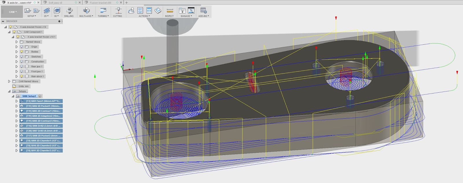


This is the remaining stock that the simulation reckons will result after these operations:

The WCS origin is the top left rear corner again. I need to be consistent with this WCS business - it's easy to get confused and try touching off on the "model top" surface, forgetting that the original origin was about 1mm above the model top before the facing (1st operation) was done. Either set everything up, press the button and work through all the operations without prevarication - or use the model top as the subsequent WCS origin for operations 2 onwards if you are intent on getting neurotic and rechecking tool lengths between jobs.
Let's do it.
First set up tools and set the height of the stock.

Anyway, it seems to fit in the available envelope (just).
Went quite well until the bit where it started to rough out the outside profile. Unfortunately, some fat, vacant idiot forgot to check the actual length of the stock, as opposed to the assumed length I modelled in CAD. Given that the difference was about 3mm, it didn't end well for the cutter:
Luckily I had another of these cutters (10mm carbide long - the last one, so must get some more....), so was able to correct the stock model and restart.


After roughing, before chamfering:

Finished article:


No comments:
Post a Comment