Dear god. I got the 4th axis working fine with the Centroid Acorn controller a week ago, cock-a-hoop, then got up the next day to sort out the electronic gearing ratios etc - and found I just couldn't control it any more. Damn thing was not talking to me using the control interface on the Servopack, - at all. I was still able to jog the machine using the front panel buttons. WTF?? What had gone wrong?
It's a really good thing I'd taken great care to connect up the wires to the interface connector, otherwise I might have ended up sticking power supply volts back up an output for instance. And sure enough, that's exactly what seems to have happened. Some stupid git had connected the 24V supply to pin 48 instead of pin 47. Easy mistake to make - but pin 48 is one of the "encoder output" outputs. This is an RS485 line driver, so seems unlikely to have enjoyed getting 24V up its ass.
I find that as I get older, this sort of thing happens more often. I guess the wheels are coming off slowly.
Have to admit, there was a bit of a hot pong, which I was tempted to put down to the 13 or so years this thing was sitting on the shelf, gathering dust. But given that the thing stopped working, that indifference was mistaken.
So what went wrong? Time to take the thing apart and see what damage I've done. Can I fix it?
Inside the Yaskawa Sigma II Servopack:


The front cover simply unclips:

And the internal PCBAs come apart easily once you remove 4 screws:

Pretty much what you'd expect. This is the power assembly. There's a separate PSU for the control circuit and a passive rectifier for the motor drive circuit (no PFC front end on a small converter like this).

There's a power module between the PCB and the heatsink.

The other PCBA contains all the IO and the digital stuff.

There's a couple of processors here. Looks as if they are Yaskawa branded. Whether they are fundamentally a Hitachi or similar processor I don't know. I expect one of these is an FPGA or similar and the other will be a microcontroller to handle all the controls, IO, comms etc.

What did you do to the line driver?
There's a fine array of optos on each side of the board. But wait, there's the differential line driver with a nasty hole in it in the middle of the pic. And some nasty, overheated resistors next to the connector on the right of the pic. All is not well but this may explain why it refuses to talk any more.

Without specialist reflow tools (which I don't have), removing a 20 pin DIP package can be tricky. I have a pair of very fine cutters that allow me to cut the pins individually. Then I can desolder each pin afterwards, one at a time.

Apart from the marks from the magic smoke, nothing seems to be damaged beyond the IC itself. The connections to the from connector are direct, so the path of destruction may be reasonably limited, you never know. Fingers crossed...

And here's a closer look at the scorched resistors next to the connector. Given the circuit arrangement, this damage looks as if it's caused by a different mechanism. Could I seriously have shafted two sets of circuits here?

What happened with the resistors??
Here's your mistake, fatty. You saw this diagram and confused the step / direction inputs with the other digital inputs. The current requirements and series resistors are quite different!!
But it's an easy mistake to make, looking at the diagram on page 6-10. Observe the resistor values at the top of the page, where the step and direction signals come in. I spy 150 ohms. Running them from 24V won't end well:
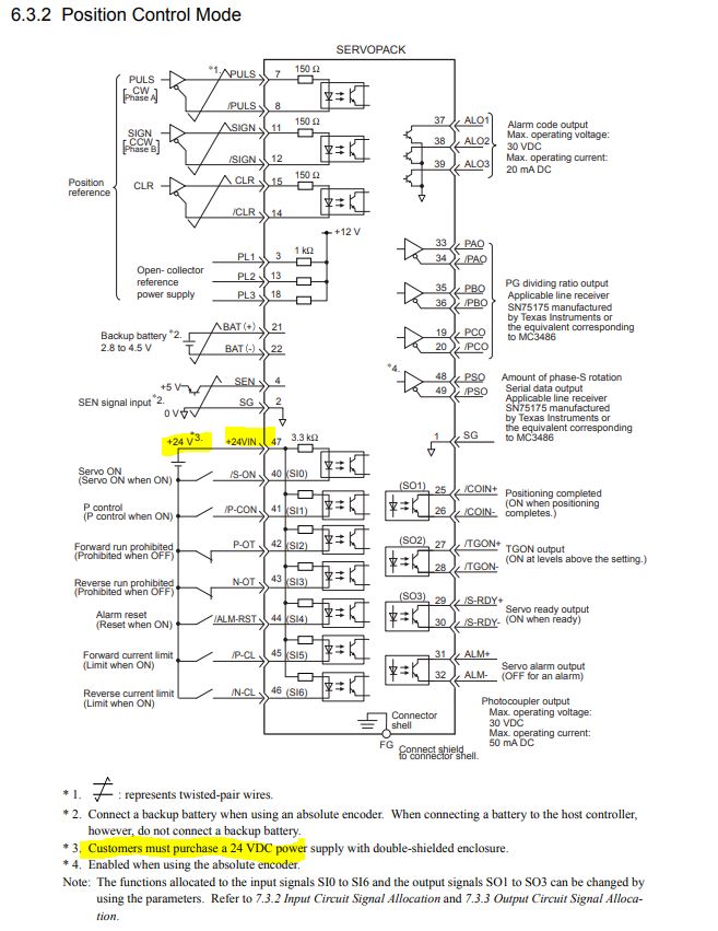
And as you can see from the "open collector output" table, there's actually a 12V protected output (1k in series) available - if I'd used this, none of this shit would have happened. Fux sake.

Naturally, my optos have a 75R resistor in series, not a 150R. And if you misread the diagram as I did, you might even think there's a 3.3k series resistor.
All I needed to do was drive the optos from the current limited open collector supplies PL1, PL2 & PL3 or fit a series resistors for use with 12V or 24V. I'll have to check to see if I've managed to bugger the optos next. For use with my own supply, 24V, I'd want around around 2.2k external series resistor to get the recommended 7 - 15mA in the opto or if using 12V, I'd want 1k.
Deep dive:
Let's have a look at some of the components at play here. After all, I may be required to replace some of them...
Datasheet for the SN75174 line driver


Choose £10 for one or £4.50 for two.


High speed opto for STP, DIR etc:
https://datasheetspdf.com/pdf-file/1089909/CEL/PS9114/1

http://www.cel.com/pdf/datasheets/ps2705.pdf

http://www.cel.com/pdf/datasheets/ps2702.pdf


No comments:
Post a Comment