I originally bought a 200W Servopack and a 200W motor with absolute encoder and brake. I noticed those features when I bought the motor but didn't realise I'd find it impossible to set up. Having
- The motor is in some way incompatible with the drive. Various of the myriad errors sort of suggested this - but it's hard to see how that could be.
- The absolute encoder was buggered or had an incompatible signal. The data is transferred by some form of high speed (serial) comms. Possibly just RS485 or similar but I wouldn't know even if it slapped me in the face.
- Some issue with the backup battery connection. Pretty certain this isn't the case but I get the strong impression the encoder is at the root of the issue and being an absolute encoder, it requires a battery.
- Perhaps the drive is buggered or has too early a version of the firmware to support the motor I presented it with.
- Fucknose. I ran out of both ideas and the will to take this any further. I have a life to live.
So I bit the bullet and sniffed out a matched pair that was shown to be working by the seller. While I was at it, I upgraded from a 200W system to a 400W one, as I was concerned that the drag torque on the harmonic drive was possibly going to bother the motor. The last thing I wanted was to end up having to buy a third motor and drive. The cost difference from the power upgrade was perhaps £20-25 or so.
The absolute / braked system is now sitting on a shelf. That's how it spent most of the last decade of course, so it should be happy there....
Tuning software:
Yaskawa's SigmaWin+ software connects up via RS232 and allows complete configuration of the drive from a PC. Being Yaskawa, the servos are capable of being configured for just about anything you could imagine using a servo motor and drive for.
First look:
Firstly, let's see what it reports finding. Yep, an SGDM-04ADA Servopack and an SGMAH-04ABA21. That's a 400W Sigma II Servopack (we are now at Sigma 7, IIRC) and matching 400W motor with 16 bit (relative) encoder. That's a good start.

I could see from the ebay photos that these were no spring chickens. The Korean seller had posted YT videos of them working some years back, when they had already been removed from equipment. Sure enough, the motor has just celebrated its 20th anniversary.

Although the Servopack itself is "only" 13.5 years old. I knew this when I bought them but the data is burned into the components and can be see via the software. At least it's still talking to us.

These compts came from equipment, that was either scrapped or had a scheduled replacement of critical parts, so likely had settings according to those applications. Best for me to start all over again. For this, there is a step-by-step wizard to guide you through and set up all the critical parameters.
Here's the user manual for the drive. And the Sigmawin+ software is here.
Flash up the Parameter Wizard:
Here's the starting screen:

First, set up the type of control and the input types etc. I want position control using step / dir inputs. Having chosen position control, the default settings are pretty much what I need.


Then there's the Electronic Gear settings. As I have a reduction ratio in the timing belt drive, I need to make us of this.

This then provides a range of "mechanical structures". The "round table" structure is what I need.

First, select the ratio. In my case that's the 34t - 60t pulley reduction.

You can then select the minimum movement of the output (in my case I think this means the chuck on my 4th axis). 0.01 degrees resolution sounds a bit silly but it's the default. I may choose to reduce this to 0.1 degrees or so later but it will do for now. I can't recall how many decimal places the Centroid CNC12 displays but it may be convenient for them to concur.
I may be ogliged to measure the final backlash for willy waving purposes, which will require a high step resolution. I can always dial it back again to something more sensible afterwards.

Then the "output pulses per rev" setting. This seems to set the required number of pulses from the Acorn to drive the motor one revolution. The "Position Control" "Calculate" option seems to match the gear ratio, presumably to avoid non integer results. I'm not absolutely 100% certain here but I'll be coming back to this later. I'll need to match this with the steps per rev settings for the 4th axis in the Acorn Wizard.

Then there's the IO settings. I've accepted the defaults here. I may choose to disable some of these, such as the POT and NOT (Positive Over Travel, Negative Over Travel) limit inputs and possibly the servo enable input.
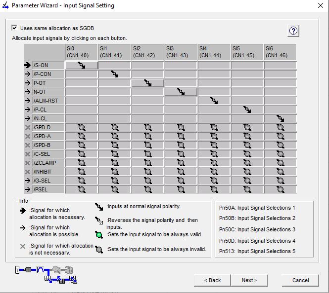
I'll have to think about how / if to connect any outputs back to the Acorn, such as the "on position" or "drive OK" type status signals.

That's it for now. At this point it's helpful to write the settings back to the drive. Pressing this "Write" button before hitting the "Finish" button is timely here.

Other wizards:
There's also a couple of wizards for optimising the PID settings, estimating MoI and searching for resonances etc. I have to say I couldn't get the Mechanical Analysis Wizard to do much. The motor makes a short noise which suggests it's being energised but I couldn't see or feel any movement. Doesn't seem likely that this actually achieved anything useful but I should worry about this later. once I've got the thing working with the Centroid controls. I wouldn't be surprised to find that the default settings are fine for my application, as I'm barely doing anything to challenge its capabilities here.

Looks impressive at first glance, although it doesn't loom like a convincing Bode plot to my eyes. Clearly I didn't achieve anything remotely useful here, so I discarded the changes.

Done:
So there you have it. I have a servo motor and drive running in the 4th axis. And a note of the settings I made on the first pass.


No comments:
Post a Comment