Spindle teardown:
Luckily, the workshop manual arrived from the US while I was away at work. Unluckily, the section on the collet closer shows a different mechanism than the one on my machine. So this leaves me no wiser about how to remove / change / adjust the collets in the spindle.
I'm also unclear about the state of the internals. I'm a little unconvinced that I want to be reliant solely on C5 collets for all my workholding, as I tend to need a range of different chucks and faceplates to get done what I need to. If I decide to make a D1-3 adaptor for the spindle nose (to allow me to use my existing Bantam chucks), I'll need to dismantle a lot of this stuff.
First I'll remove the hydraulic actuator. Whether it goes back on or not remains to be seen but it's not going to help me to dive into the closer mechanism where it is at the moment. So off it comes...

There's a large thrust bearing, complete with cast iron(!) body. This pushes the conical body into the 3 jaws to release the sprung collet closer drawbar. It seems likely that that massive cylindrical body contains some form of spring(s). The ragged tube sticking out of the conical body is the drawbar and it has been buggered by the use of crude and excessive force which has resulted in a lump being broken off the drawbar and distortion of what remains. Consequently, said conical body won't slide off any more.

Anyway, this locking pin is held in place by the spring plate you can see here. It drops down into the central bore.

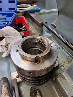
...and locks the drawbar from rotation. So this shows how you adjust the collet and drawbar to the correct pull-in. Presumably by turning the protruding (now broken) end against the threaded collet. Conversely, if we unscrew it, the drawbar will come out. Bingo - here we are:


Not a great photo but you can see the tapered bore of the spindle collet throat.

I'm expecting that the nose (throat) piece will be removable, resulting in a larger bore. I seem to recall 1-75/8" or so being mentioned somewhere, which would mean about 50mm.


Here's the drawbar with its male-female adaptor for pulling the collet. You could imagine a different adaptor for a different collet system - there was a choice of 2 types.

So - how to remove this fucker?

Obviously these 6 fixings need to come out.

It's not actually thread on but needs something to get it moving. This C spanner did the trick.

Those levers push against the face of the abutting disk

..this one. Which has 4 massive Bellville springs.

Question is - how to remove this spring assembly? Can't see any other fasteners that can be accessed. Sure enough, if I look into the bores of the 6 threaded holes I've just cleared, there are another 6 (grub) screws. But nothing happens when they are removed, so the whole thing must be threaded onto the rear of the spindle itself. That's a compete arsehole, as it's massively tight and the only thing I can use to unscrew it is the C spanner again.


Well finally I managed to unscrew the entire assembly by using the C spanner and a dead blow hammer - developing a blister on the palm of my hand in the process, FFS.

At least it's off now and TBH I can't see myself refitting it any time soon. Unless I was planning to do some sort of repetitive production run, I'd want to be using a manual chuck for workholding. Certainly, the process of fitting and adjusting a C5 collet that can only take a limited size range doesn't feel appealing.
Here's the rear of the spindle. It's not clear yet what is happening here, so off with the crosshead screws...

The thing that might almost look like a keyway is actually a pad for locking the threaded collar - which presumably holds the spindle bearings tight. I will leave that for now, although I may need to revisit this later when I investigate the state of the spindle bearings.

Well, TFFT. It look a while to figure that out and dismantle all the collet closer gubbins.
So now I have a much simpler rear end on my spindle. Also, I don't see any future in the hydraulic closer itself, so that should simplify life a little. I will likely just leave the spindle as it is now. You never know, this might also allow me to shorten the machine by a foot or so...
How about a chuck for the spindle?
Firstly, what have I got here? It's not a spindle nose I'm familiar with. From smalltools.com, there's a guide to spindle noses.
Looks as if mine is an A2-5 style:

Here's an A2-5 adaptor for a fancy chuck. I think I'll machine that down to form an adaptor for D1-3 chucks. That way I'll be able to use my collection of chucks, rather than start all over again. Job done - it will cost me another £150 or so but as a starting point for the spindle tooling, it needs to be a decent a quality item with enough meat for me to machine the D1-3 features into it. Using my calibrated eye, it looks almost man enough for that but there's no easy way of telling until I actually handle it.
Enough of that. I seem to have a plan for the rear of the headstock, so let's get back to the X and Z axis drives and ways.


No comments:
Post a Comment