Stock taking:
Having survived the machine moving buggerage without loss of life or limb, it's time to take stock of what I have in front of me.
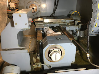
From the tailstock end. The servo motor is underslung and clearly drives the Z axis ballscrew through a toothed belt. Presumably the cover is protecting an encoder on the end of the ballscrew
That's a big fuckoff drag chain. It has to be, as it's housing several hydraulic hoses and a bundle of control wires....
...that feed the ATC unit.
The spindle nose has a 5C collet taper. There's one still in place. I believe you can also remove the nose piece (held in place by 6 socket head screws) and fit a proper chuck. At least the mating face will have been protected from rust in the meantime.
Here's the back of the headstock. I'll remove the lower cover shortly so I can get a better look.
Here's the collet closer, which is hydraulically operated. Also a spindle encoder with 1:1 ratio and a pneumatic filter / regulator. Interesting - what exactly is using the air supply?
Various solenoids for controlling air and hydraulics
This is the collet closer. The conical nose if forced into the fingers by the lever. Does this tighten or loosen the collet? I need a manual to find out unless I fancy stripping everything down. And I imagine there may be some big springs involved....
There's the big RSJ framework, with the control cabinet hanging off the back. Simply removing that will be a major task due to the sheer weight of the thing.
There's a compressed air feed pipe across the top. Although it's not connected at either end, there's a socket at the bottom of the pipe, next to the air regulator inside the machine. I think we can guess how it was connected up.

Where did this thing come from?
I got lucky here, as I found an auction listing that shows this machine being flogged off:
It's definitely the exact same machine, as the stickers, serial number (#166) and even the manuals are the same. Bizarrely, the auction states that the machine is located in Oxon (in Oxfordshire). Judging by the scarce info on the auction site, the hammer price was passed, yet there was no final price listed. All the other sales showed the final bid price. Strange. This was almost exactly 3 years ago - Feb 2019.
And yes, even the manuals are the same.
This asset sticker, found on the rear of the control cabinet is a bit more helpful. The "University of The West of Scotland" is based in Paisley, east of Glasgow. It was formed by the aggregation of a group of colleges with the University of Paisley, including Bell College, which is based in Hamilton. Given that Hamilton seems to have been where this machine spent most of its life, it seems unlikely it would have been driven all the way down to Oxon, then all the way back to the Scottish borders to its last home where it had started.

What was in the cardboard box?
Luckily, the original documentation shown in the auction pics was still present and made it to me intact. Unluckily, it turns out that the manual is actually a programming manual for the antiquated controller. And even more unluckily, the 2 additional documents are simply copies of that original factory manual. As I will be dumping that part of the system, these manuals are of no value to me other than passing interest. And a scan of the contents give very little or no information about how the machine is constructed of how it operates. I was suspecting that might be the case.
Aha. One point of interest though - "Bell College of Technology"!
Bloody hell. Punched tape used for program storage and recovery:
Also in the box - the clamps and blocks for tool holders, used on the turret / carousel.
And 4 quaint (ancient) indexable toolholders. It looks as if 2 of them may be almost usable (the bottom 2).
Here's the main incomer power isolator. It looks as if the last owner removed it for some reason, otherwise it would surely be rusty by now. It's supposed to prevent you powering up the cabinet with the door open.
What's inside the control box?
Let's look inside the control cabinet. This could be interesting - if you are a museum curator perhaps!
Firstly, WTF is this thing? It's accessible through a little window at the rear of the machine.
Yes indeed - it's the punched tape reader (and possibly writer?). I wonder what data rate this could achieve at full chat? I'm imagining millibaud, if there is such a unit.
Now, into the guts. Corr, what a box full of stuff. The spindle controller top right, controller "PC" bottom left. Servo amps in the middle. Mains contactors, fuses, EMC filters etc bottom right and middle right. Then a veritable forest of relays and barrier strips elsewhere. 2 three phase transformers, the smaller of which appears to be a later addition, to match the system to the local mains supply perhaps. The tape reader thing is just visible top left of the pic.
These are the 2 servo amps for the X and Z axes, along with their rectumfrier / smoothing cap etc. Looks like a couple of filter inductors at the top, presumably to filter the power supply voltage, or possibly the outputs of the servo amps.
This is the microcontroller / CNC controller brain, although by today's standards it would be a village idiot.
Here's the controller for the 5HP spindle motor. It's a giant brushed DC motor, so this unit has 3-phase input and DC output. The front cover is actually held on by Velcro - I guess that was high tech at the time this machine was manufactured.
Here are the 3-ph inputs and the DC output.
There is a nest of PCBAs running this thing.
The date codes on the compts mostly say 1978 and the caps appear to be Siemens if I recognise the trademark correctly.
Each PCBA hinges forward and out of the way, without needing to be disconnected. Even the ribbon cables are long enough to allow that.
Here's the nameplate. Built in 1979. Model number D200/85. Input 190Vac(?), output +/-200Vdc. 85Adc continuous(?); 142A intermittent; 340A for 200ms(?).
The warning sticker tells us that there is no galvanic isolation of the DC output from the supply network.
The final (rear) board is this one, which seems to be the gate driver board. I assume it's some sort of SCR scheme, as I doubt IGBTs were mainstream at that time.
Here are the 3 upper boards, hinged out of the way. Quite a system!
Now let's look at the controller:
Wow. Lots of PROMs and EEPROMs.
Those are 16kb EEPROMs.
..and these are 4kb static RAM. PCBAs designed by Xycom, whoever they were.
This looks like a 3-channel motion controller.
These are ADCs. Not certain what they are measuring, as the encoders are digital.
Perhaps digital I/O?
This looks like the actual microprocessor boar, judging by the 2 crystals. The big device at the top right is a MOSTEK MK3880N-4, which is an OEM version of the Z80 micro.
The NEC D8259 is an interrupt controller and the 8251 is a sort of UART:
From what I can tell, the operating system is an early version of IBM's O/S2. I can tell you for a fact that this particular instance of that OS has breathed its last.
The servos seem to have been taking their supply from the 70Vac taps on the 3-ph transformer. That suggests a DC bus voltage of around 100Vdc. The DC bus cap had a rating of 150Vdc, which could work. I will need to take a closer look at the servo motors but as the simplest solution may be to leave them in place and use modern digital (DC brushed) drives, I will need to work out what voltage they want to see. But this is a good start.
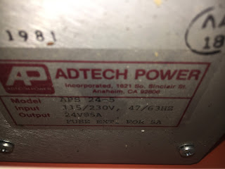
This shoebox-sized PSU is simply driving the 24V controls, which in this case seem to be a forest of relays. I guess they may be pretty hungry but even so, this only a 5A / 120W PSU. An equivalent modern DIN rail PSU would only be 1-2" wide. Note the date - 1981, which is about 2 years before I started working in SMPS PSU development.
Here's a glimpse of the X axis servo motor, slung under the rear of the saddle. Presumably there will be a tacho output and temperature sensor in the conduit, as well as the DC power cables.
The Z axis motor seems to be hidden away under the cast chassis / chip tray.
What about the toolchanger?
There is little more than a differential encoder and a pair of switch(?) contacts, in terms of the electrical connections to the toolchanger assembly. The controls must be fairly simple.
Inside, there's a reduction gear and a locking pin, rather like the park lock in an automatic transmission. Those 2 switch contacts are indeed connected to a microswitch that presumably detects the home position.
Here's the locking pin and the microswitch. I will need to investigate this more closely at some point.
At this stage, it made sense to drag the tool changer out of the machine. I will need to figure out how it works and what if anything I will need to do to modify it.
There is a single hydraulic solenoid here, so removal requires little more than snipping a pair of wires. These funny white cylinders are everywhere on this machine. They are RC snubbers, intended to damp out any switching transients when the solenoids are actuated. They can fuck off into the bin - for one thing, they must be a reliability risk after 40 years in the field.
It seems these solenoids are actuated by 110VAC. There are similar ones next to the valve block for the tailstock and collet closer behind the headstock. It was going to be either 110Vac or 24Vdc.
Another one of those damned snubbers
I see no reason not to remove these connections. Apart from the microswitch on the indexing gear, the others are all going to the encoder. Looks about right for a differential encoder, with the right number of wires (9) for A+/A-, B+/B-, Z+/Z- and +5V / 0V plus GND. It's a Sanyo encoder, so should be easy enough to look it up.
And sure enough, that funny cover on the end of the Z axis ballscrew reveals a conventional encoder. The system claims "full closed loop control", which in their case means the encoder is on the ballscrew, rather than a linear position encoder.
Here's the hydraulic valve block on the back of the tool changer.
Let's have a look behind the operator panel:
Dear god - a Motorola VDU.
The panel itself is just an acrylic panel with industrial switches and a pluggable harness. I may or may not end up using some of those but I expect I may fit a touchscreen display there, so there may be little space remaining for actual switches beyond power, e-stop etc.
Let's remove the compressed air assembly. The only hoses coming from this emerge in the vicinity of the spindle chuck but are currently left hanging. I'm guessing that there was once a pneumatically operated 3-jaw chuck. If I fit a proper chuck, it's likely to be a manually operated one but I'll keep the regulator assembly anyway.
Now, look at the drive and hydraulic systems:
Sod it - I'll get round to this later. For now I will look at stripping out all the shite from the control cabinet, then removing the cabinet itself, along with the massive steel framework.


No comments:
Post a Comment