Determining the X offset for drills in the Tree (and other CNC lathes) can be a bit tricky, given that the drill is actually mounted in the turret (cross slide). For this to work without breakage, you need to determine the X coordinate of the drill. This is then entered as the X axis tool offset and ideally it would be constant for all of the drill / boring bar mounts on the turret.
There are a few ways to do this, such as trial and error (by eye etc) ie spinning a piece of stock and moving the turret in X until the tool (drill) tip scribes a point rather than a circle. Another way is to use a concentric indicator, as often used on non-CNC milling machines that don't have electronic probes.
I got one of these before Xmas. Not much more than an ebay / Aliexpress version (and almost certainly Chinese made) but perhaps subject to slightly better quality control.
In simple terms, you probe the outside or inside of a concentric, cylindrical part, then move the turret to minimise the indicated eccentricity. In my case, I can move the turret in X but not Y (ie vertically up and down). Given that there is no evident means of adjusting the turret in Y on the Tree, I have to hope any error isn't significant.
Let's go:
First, set up the indicator so that the main body is deadly concentric. Initially with this Kurt-badged Chinesium thing...
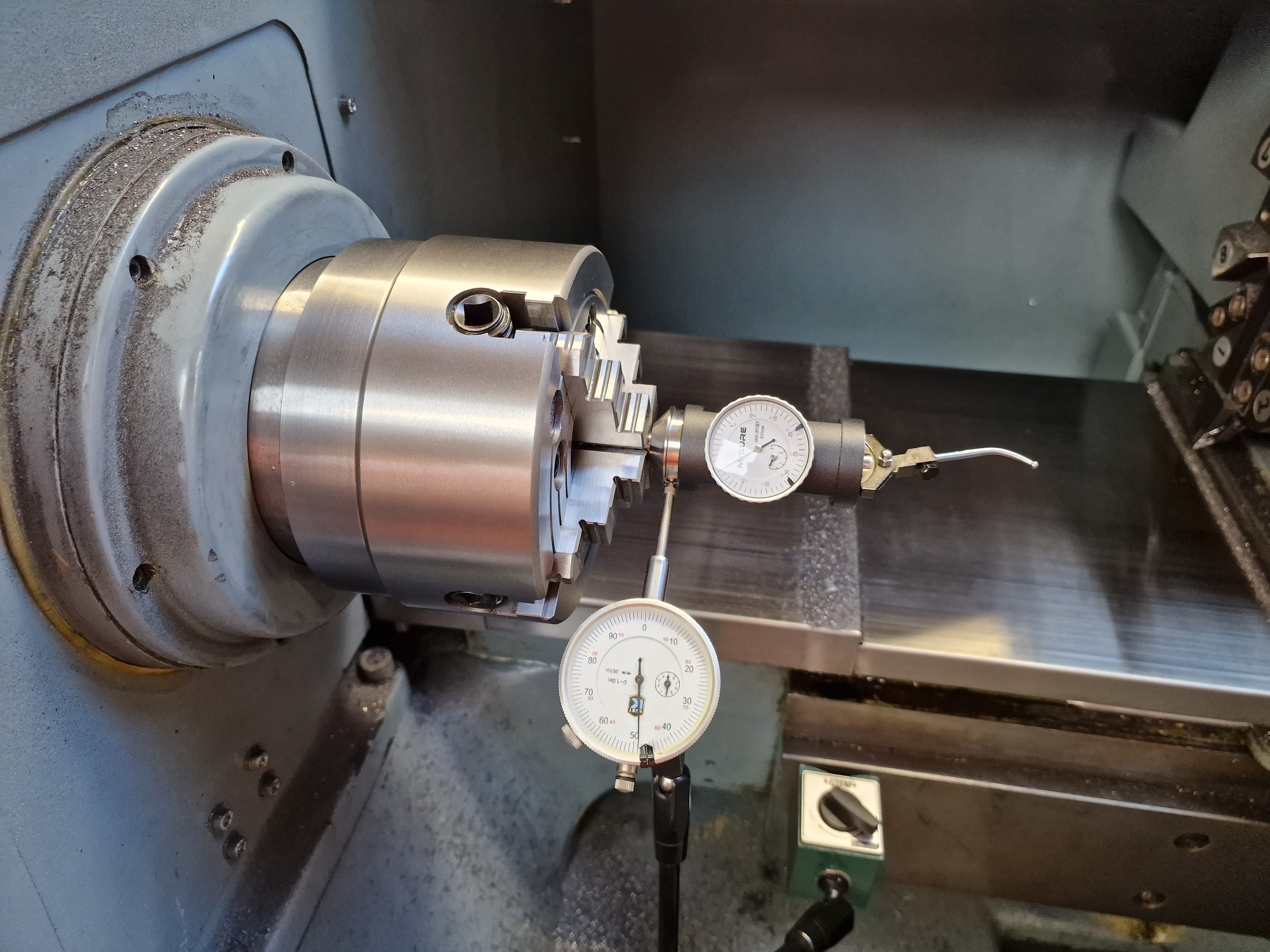


With tool #6 and its offset selected (T0606) - and X axis zeroed, this is what you'd hope to see. For instance if you loaded a drill in tool #6 and asked for it to positioned in line with the spindle axis:

I may be forced to try out drilling at some point in the near future. No excuse now...


No comments:
Post a Comment