Saturday, 16 March 2019

Z axis - fitting, fettling and configuring

Machine fitting:
Right. Everything looks good to go, so let's get it on. It's not going to be just a question of bolting stuff on and powering it up....

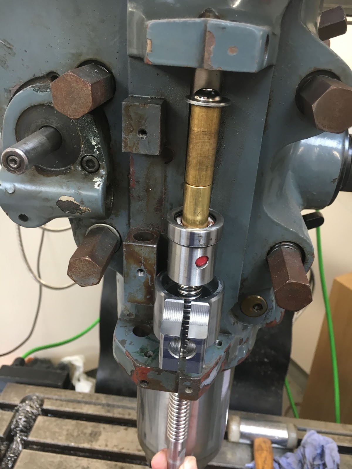
Firstly, fit the extension piece to the ballnut protector, so I can slide it onto the ballscrew without my balls dropping, fnnaaaaar!!


In place, ready for the ballscrew:


If I could get the ballscrew to drop down into the yoke, I'd be able to remove the tool. However, the yoke is sticking out too far. I forget how / when I measured the dimensions on this machine but it was certainly at least 4 years ago. Bottom line is that some careful measurement shows I need to remove 0.270mm from the cylindrical face on the back of the yoke, where it mates against the quill.


Fettling the yoke offset:
Take it off again and mount the yoke on the lathe faceplate. The tip of the internal grooving tool is sitting on the axis and I can use the graduated cross slide dial to move it back to the required 42.16mm, at which position it skims the existing surface of the yoke. Then move a further 0.73mm. 


Checking it's coaxial with the lathe:


Off we go. The outer (tailstock end) face first, using power feed away from the headstock.


Then the faceplate end, hence the internal grooving tool to reach round the other features, using power feed towards the headstock. The tailstock is being used to help me return the tool to the correct position.


Woooh! 


One benefit of liberal application of WD40 is the mirror-like reflection which helps to gauge how close the tool is to clashing. The carriage stop can't be used, as it would clash with the faceplate.


It's pissing down outside and these wood pigeons look fed up. They look ready for the pot...


Some sums:


Clearance for the yoke: A bit of bodgery to provide a bit of clearance between the yoke and mountings for the trip mechanism scale, using the angle grinder. A bit of polythene to contain the nasty grit, then try it again. We'll call this "machine fitting".


Back together again. That's better:


Pleased with the belt tensioner. I designed that using the Solidworks belt tool which has positioned the tensioner perfectly.


Preloading the thrust bearings and flashing it up:
The final step was to shim the bottom bearing to give a bit of preload without buggering the thrust bearings. Some 0.015" shim steel was spot on. Now wire it up and see if it flies. I had some test leads wired up from before...


Setting the parameters:
Yep, seems to work nicely. Obviously the scaling isn't right, as it still has the parameters from The Shiz. That had 1:1 belt ratio, 5mm pitch and CNCdrives servo drivers. This system has a Leadshine closed loop servo, 18:22 belt ratio and 4mm pitch.


Quick ballpark check on the backlash. Seems to be around 60-70um, which is probably about what we should expect with this crappy Chinesium ballscrew. I might look into this a bit more closely at some point:


The Leadshine motor is set up for 8000PPR:


The sums are fairly simple: 4mm per rev of ballscrew; 18:22 belt reduction and 8000 pulses per rev.

(4000 um / 8000 pulses) x (18 / 22) = 9 / 22 = 900 / 2200:


Axis #27 (numerator) = 2200

Axis #28 (denominator) = 900


Job's a good 'un.


There. Need to make up some proper wiring for the motor and then look at fitting the limit switches....


Saturday, 9 March 2019

Bridgeport Z axis - my design concept and a review of the existing parts

My design concept for the Bridgeport Z axis:

Most Bridgeport conversions connect the Z axis ballscrew to the quill by means of a yoke (bolted to the side of the quill) which slides up and down in a slot in the quill housing. Due to the shape of the head casting and the various features littering the front of it (associated mainly with the downfeed trip mechanism), the yoke has to cantilever out a fair way from the quill. This is a weakness in the design concept (literally), as there is only a small bolt (around 3/8" or 10mm) to hold the yoke to the quill. 


My cunning stunt uses a 16mm ballscrew that occupies the space taken by the feed trip adjuster screw. This concept was one of the first parts of the conversion I designed, as the X and Y axes seemed fairly straightforward. So when this was first modelled up (when I was living in Canada in 2013), I was using Solidworks. Here's what I came up with. I think this assembly view may have been from a subsequent trial in Onshape when I was beta testing it. But the design is unchanged.


The main features are:

  • 16mm ballscrew ("SFU1604", 260mm length) replacing the feed trip screw, supported with thrust bearings at top and bottom. I bought this from AliExpress in March 2014.
  • Leadshine closed loop stepper with integrated driver ("Integrated Easy Servo"). I selected the biggest version (iES2320 - 2Nm) which should be more than adequate for my machine and application. 
  • Toothed belt drive underneath the quill housing. Sounds dodgy but in fact it won't compromise the quill movement or clash with the toolholders. The alternative (belt drive at the top of the ballscrew) would be tricky and lead to a loss in quill movement which is already a problem with these turret machines to start with.
  • Jockey wheel belt tensioner, rather than the usual slotted bolt holes. There's no reason not to fix the motor and take up the slack if you design the belt linkage carefully. One rather nice feature in Solidworks that hasn't been implemented in Fusion 360 (yet) is the chain / belt assembly tool (see Pootube video below). I used this to set the precise position of the motor relative to the ballscrew once I had selected the initial belt length. As toothed belts only come in fixed increments, you have to design your system around the nearest belt length rather than the other way round. The result is better than I got using the more commonplace "pulley centre calculator" tools.
  • The original DRO scale sits in front of the assembly (its original position didn't seem to clash with the new system, so it would seem rude not to retain it).
  • Steel yoke with split / pinch bolt to allow the ballnut to be disconnected from the quill. Wasn't sure how useful that would be but it also allows a small yoke, unencumbered by the need for fastening bolts. I machined back the original (hardened) flange on the ballnut to minimise the size of the thing - in the process the fixing holes disappeared in a cloud of sparks.
  • Omron proximity switches for limit and homing signals. I bought these off ebay and discovered that they were actually a mixture of NC and NO versions. Given the pricing (from China), that wasn't a problem - I'd bought 20 of the buggers, so had plenty spare. Not convinced they will be repeatable enough for use as the homing switch but if that's the case, I will replace that one with something more suitable. But they will almost certainly be fine for the "shit or bust" limit switches.

Solidworks belt / chain tool:


Here's a good demonstration showing how to use this tool.


Cross Section View of Z Axis Assembly:


Here's the section view:


Front right view: 


Underside view (with DRO scale and proximity switches hidden): 


Front left view: 


And as this was the most interesting / challenging part of the build, it was also the first assembly I machined up. 


"Here's one I made earlier" - yoke


Although I'd actually made the parts by the end of 2014, I imported them into Fusion 360 last year so I could remake the yoke in steel using The Shiz. My original yoke was made in loominum using manual operations. The machining of the steel version is documented in this very same blog. It's already fitted to the quill.


The finished SFU 1604 ballscrew:


The main bracket - underside:

Yes, it had to be sawn in 2 and welded back together after machining, as my lathe isn't big enough to swing a part this size - doh!! The slot is for the sliding tensioner wheel.


The main bracket - topside:

The welding looks particularly shite here but it's largely due to the lighting, honest.


Ballscrew with upper and lower bearings in place:


This brass thing is the means for fitting or removing the ballnut from the ballscrew without all the balls dropping out. Its diameter is the same as the minor diameter of the ballscrew.


The male thread fits into the similar length of brass that is currently in the ballnut. I remove the dome headed M6 fastener / washer and screw in my brass adaptor instead. That allows me to slide the ballnut directly onto the ballscrew.


The main bracket fits under the feed trip mechanism housing:


And the motor sits on the main bracket....


...something like this:


This is the lower bearing, viewed from the top side:


There's a spacer to ensure the bearing is firmly clamped against the casting:


Like this:


Finally, I made up this tool for tightening the square nut to the end of the ballscrew:


There are a few other parts in the kit (proximity switch targets, proximity switch bracket, DRO scale spacers etc but certainly I seem to have made up most of the parts - and not lost any of them.


Next - slap it together!

Yaskawa V1000 VFD up and running


With the limit and home switches set up and homing etc configured, it seemed a good time to test the VFD installation. I'd wired this up last year when I built the cabinet and rather pleasingly it seems to work out of the box. Just needed to go in and set the motor parameters etc and the job's a good 'un. The TEC motor seems to make a good loudspeaker using the default settings, so I set the carrier (switching) frequency to the highest setting (12kHz?) which pretty much makes it ultrasonic for old gits like me. There's a nice squeak when first enabled but the carrier frequency rapidly rises to a more pleasant place.


With these VFDs, you can develop full torque at stall (0rpm), notwithstanding the thermal limitation on extended operation which I believe is protected by the default thermal model inside the VFD. But for the kind of slow speed operations I'd expect to be doing (tapping and drilling), that's unlikely to be an issue. In the limit (so to speak), it would be possible to either change the thermal parameters for the motor, use the built-in motor thermistor for feedback of the actual winding temperature (yes, there is one) or ultimately fit a static fan to genuinely extend the thermal envelope. Really not an issue for me....

Love these Yaskawa drives!

Saturday, 2 March 2019

Temporary homing switches for the X and Y axes, plus initial axis scaling and backlash tests

Temporary homing switches for X and Y:
I can't decide on suitable homing switches for the X and Y axes yet. These need to be reasonably repeatable and precise, since they ensure you can pick up the machine coordinates where you left off, in the absence of a more sophisticated absolute coordinate system. Failure to achieve that can lead to toolpaths becoming offset from each other if you have to power off or force a reset. This in turn will bugger up your work.

It will be some time before I have the Z axis system in place, so for now, any inaccuracy / inconsistency won't be critical. So I have plenty of time to decide what to do about "proper" switches.

So here's the (temporary) Y axis homing switch in place. I previously ran a 4 core screened cable to the limit switch, so I just need to run the switch connections into that switch body. The homing switches will be NO, unlike the limit switches which are NC.


I like drilling and tapping holes in this machine.


And here's the X axis homing switch. I had to extend the roller spindle so it would contact the movable stop without said stop interfering with the actual limit switches. It's pretty ropey but for now it just provides a basic level of functionality.


All done now - and connected up inside the cabinet. The homing functions work nicely. This is it at the X and Y home position:


Check axis scaling and backlash: 
The ballscrews are both 5mm pitch and I have a 2.5:1 reduction in the toothed belt drive. That results in a very simple ratio for the number of pulses per mm travel. However, having programmed in the parameters in the "Axis Parameter" area, it's sensible to check the result. Rather conveniently, I previously fitted a 3 axis DRO to this machine and it's really not worth taking the scales off, so I have a simple means of directly comparing desired movement against actual movement. 

Time to remount the display head. I took a look inside this recently and although it's a bit Chinesium, it didn't look hazardous as such. Besides, I have a good strong protective earth and the workshop circuits are protected with RCDs.

Here we go:

The way to check for backlash on each axis is to creep up on a nominal position (eg X100), note the measurement on a "real" DRO, then overshoot the position (eg to X110) and creep back to the same nominal position (X100 again). Any backlash will show up as a difference between the "real" DRO and the CNC's DRO display. 


Homing repeatability:
Finally, having checked the scaling is correct, it's a good time to see how repeatable the homing function actually is. 

The X axis seems to be repeatable to within 20-30um which is rather better than I'd expected. However, the poor tolerances and resulting slop in the switch mechanism suggests I'd be foolish to count on that.


The Y axis seems a bit worse, most likely due to the different actuation method and some differences between the 2 switches themselves. 


Still, it seems to be a reasonable result.

Some buggering about with max feedrates, accel rates etc and I seem to have a reasonable result for now. 

What next? 
Before I start on the Z axis, there are a few things to finish off:

  • Refit the X-axis DRO scale cover.
  • Do some tidying up of the cabinet wiring after the recent limit / home switch work.
  • Possibly wire up the spindle VFD.
  • Connect up the servo error line back to the controller. Currently, if either of the servos bomb out, the controller has no means of knowing. Not ideal.
  • Fit comms / diagnostic cables to both servo drives. I have 2 Dsub cutouts in the cabinet that are ideal for the job. Just requires making up a couple of simple tails.

Bantam CNC - final homing and backlash optimisation (phew) - index homing no more.

There's still some work to be done on this homing accuracy business. Let's see if we can crack it finally. The decision to use the C...