Sunday, 25 February 2018

Machining the X axis cover - finally. And a close escape!

The CAM for the X axis cover has been ready for a week or so but I've had a few distractions along the way, not least managing to bugger my back when putting some masking tape on the wall during some painting. WTF?? Bags of cement yes, tape on wall no.

Want to get this out of the way before I start to bugger about reworking The Shiz, removing the Newker controller and fitting the Centroid Acorn system instead. It should have been a quick job but things haven't worked out that way.


Last minute sanity check on tool lengths, using a 10mm (broken!) cutter shank:


Couple of issues fixed before starting:

  • Many of the plunge and ramp feeds were pathetically slow. I corrected that in the tool library where possible. Values like 333m/min needed to be in the 1000-1500 range.
  • The deep drill cycle was taking forever. Changed to peck.
  • The 4.5 drill is now in an ER16 collet, so needed to change number to T05.
  • I went for conventional milling on the chamfer operation. DCTTeacher suggested that as a means to improve the finish. Let's see how it works out.
Finally donned the rubber pants and went for it.
  • The drill cycle was still pathetic. The feed height was 5mm, so it started pecking in air way before it got anywhere near the surface. And the peck depth was only 1.125mm, at which point it would retract and start again. Changed feed height to 2mm and peck to 3mm.
  • The drill didn't break through. Although I'd selected "drill through bottom", for some reason I'd selected a 3mm offset (WTF??). Changed that now and also extended the hole 1mm beyond the stock bottom.
  • The 6mm HSS slot drill sang a bit during the boring operation. But it WAS dry, so perhaps I shouldn't have been surprised.
  • The main operation was the external 2D contour. As I recently removed the enclosure and didn't want to make a complete mess in the workshop, I tried to make do without coolant. However, the tool got hot and swarf ended up welding itself to the tool. Luckily I stopped the machine before the tool pinged but it was obviously a very close run.
  • The chamfer was better on the top edge but still shit where it met the vertical face. I don't think I've got the feeds and speeds right and it's possibly not the best tool.
  • The 2D adaptive for the bolt pockets left a 0.5mm "axial stock to leave". Stupid boy. So when I made the finishing pass (2D contour), it left a pip in the middle of the pocket. The countour operation doesn't clean up the horizontal middle of the face, only the vertical surface.
Here's the cutter. More like a stir welder than a cutter!!


And the result:


But despite all these issues, it actually went well. No lasting damage / evidence once the job was done.


I crudely snapped off the larger piece of stock from the tabs. Some saw / file work is still required to complete the job:


The pockets came out OK, apart from the 0.5mm pip I mentioned....


The hole chamfer was defined in CAD. Possibly a bit bigger than ideal, when positioned right next to edge chamfer.


I didn't do anything special in terms of cutter radius compensation so I was surprised and pleased to see that the 48mm diameter bore appears to be pretty darned accurate. Yes, I've checked these calipers with my slip gauges and they are actually pretty accurate themselves.


These were taken before I removed the work from the fixture


Job done!

Friday, 23 February 2018

All-In-One PC for Shiz Acorn?

I need a PC to run the Centroid CNC12 control software. According to their website, the minimum recommended spec is a single thread benchmark test score of 1500 according to this benchmark. That tends to imply something like an i3 processor as a minimum, so there's a good chance my collection of vintage PCs may prove unsuitable. 

I'd like a low power processor that doesn't require a tornado stream of cooling air with a noisy wasps' nest fan to provide it. Given that I'd rather not have to go out and buy another new PC, do I have anything suitable already?

For the LinuxCNC machine, I bought a passive cooled Jetway JNF9C-2800 barebones motherboard which runs from a single 12V supply and is powerful enough to run LinuxCNC without any difficulty. This was back in 2014 and they don't do that one any more but there seems to be a very similar one stocked right now - the JNF9D-2550. They both use the Intel "Cedar Trail" Atom processor. The D2550 1.86GHz processor comes in with an abysmal 303 score, so it's not even marginal, simply and totally way out of its depth. Either the Centroid software is doing a lot more computation than LinuxCNC and/or the OS (Windows 10) requires a lot more processing power than Linux. I suspect mainly the latter. So that's a non-starter.

One option that is recommended by Centroid is the Intel NUC7i3BNK "mini PC". The Intel NUC family is available with a wide range of processors and the recommendation from Centroid is the i3 7100 (2.4GHz, dual core "Kaby Lake"). That looks like a nice solution but would come in at about £230, just for the bare bones. By the time you add 4GB (minimum) of memory and a 128GB M.2 SSD, the total creeps just over the £400 mark. Then you need to add a 16:9 touch screen, ideally around the 20-23" size. The Asus VT207N comes in at £180 on a good day, so the total price is going to end up close to £600. Hmm.

The other option offered by Centroid is an "All In One" (AIO) PC which combines a touch screen with a PC in the same sort-of-display housing. They actually show a Dell AOI on their website but it seems to be discontinued. Presumably they offer something similar, unless they have a load of old stock. At $800, it isn't a bad solution but that's still too much for me and I'd get crucified by the carriage, duty and tax payments on the way into the UK. However, there are a couple of alternatives:

Shuttle (German) do an AIO (the 50V6U3) that seems to be aimed at the commercial / light industrial market ("for POS, POI, Kiosk Applications"), with the i3 7100 processor and an IP54 screen. It's a fanless machine and they claim it's happy to run 24/7. The main downside is the small screen (15.6"), high cost (£600) and limited availability (I can only find it at one outlet). No cigar there, then.

Then I spotted the MSI Pro 24 6M All In One (AIO) PC. This also appears to be aimed at professional applications like POS and although it seems to retail for £1000-1700 depending on the model, I found a refurbished example with 128GB SSD, 4GB memory, Windows 10 and a claimed 12 month warranty for £430. Given that it seems to be a recent model, I'd guess it probably isn't very old. As the name suggests, it's got a 24" screen (and it's got the recommended 16:9 screen aspect ratio), so should be pretty nice to use in the workshop environment - better larger than smaller, up to  point.

So that should take care of the PC, display and motion controller. I also have a suitable cabinet, so the bones of the replacement system are falling into place.

New cabinet for The Shiz!

All change at Shizville, as mentioned in the last posts!

  • The current Newker controller will be relegated to the Blidgeport conversion. It will be absolutely fine for that purpose, combined with the Leadshine and DMM Tech drives I previously designed in for that project.
  • I stuffed everything into the original control console, in the process jettisoning the original (massive) cabinet. However, it's a bit too tight for comfort, it's a complete pig's ear and if I'm to use a touch-screen PC, why would I also want a bloody great box sticking out at head height? It's so damned big and heavy that I had to weld up a massive support cantilever. That in turn made the enclosure design a messy challenge.
  • So the new Centroid Acorn-based system needs to reside in a traditional cabinet, with just the keyboard and monitor (or all-in-one PC) outside, next to the operator.
  • Bought a Europa Components enclosure STB605025 (500mm wide, 600mm high, 250mm deep) from CPC. 
  • Recovered one of the original brackets that supported the massive cabinet, cut it down and wopped it back on the machine. 
  • Then did the required drilling, tapping etc to fix it in place. Looks good.
Straight out of the box:

Includes back plate, handles etc:


Shorten the original cabinet top bracket on the band saw, so it's the same width as the new cabinet:


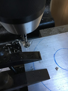
Drill out an additional fixing hole:


Debur!!


Fits nicely:


Very useful instructions, even if they are upside down:


Fixed in place. It's actually dead vertical but the iPhone suggests otherwise:


There you go, ready for stuff to go in:


New arrival - Centroid Acorn

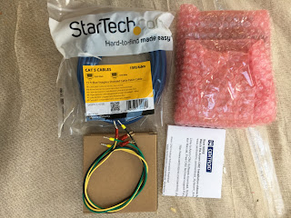
It arrived this morning. Small package.

Well packed:


Bubble wrapped PCBA:


PSU wiring (except mains), Ethernet cable and PSU in brown box:


It's a MeanWell PSU, which is pleasing - they are a good Taiwanese brand. 24V / 0.6A (that's about 15W):


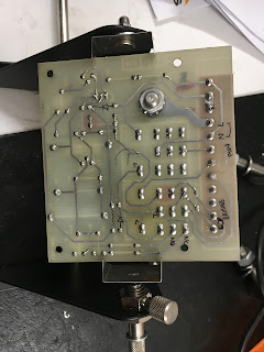
Underside of the PCBA, showing single-sided component placement:


It's all SMT components apart from the connectors. I don't think much of the through-hole soldering. I'm guessing the PCBAs were assembled (in China?) and the connectors (including the header sockets for the daughterboard) hand soldered in the US by untrained grunts. I'd hope / expect to see the flux removed with IPA and a brush at the very least. However, I've seen worse and it's not a serious issue here.


Doesn't look bad from the top. The Beagle Board Green plugs onto headers in the middle of the board:


That's it for now!

Newker (China) vs Centroid (USA) - all change at Shizville!!!

Where we are:

I've made good progress with The Shiz over the last year or so, between giving it a mechanical overhaul and replacing the ancient "Micon" / Parker Hanifin "Digiplan" CNC controller with modern electronics. This has gone pretty well - on the mechanical front, I've not found any significant damage or wear, the machine is in very good nick for its age and any repairs I've carried out have been to address water damage in some of the bearings.

The electronics update has also gone well. I retained the original SEM DC brushed servo motors and installed new, digital drivers from CNCdrives.com For the actual CNC controller, I bought one of the "sort of Fanuc clone" controllers that are available from a variety of Chinese suppliers. 

Chinese controller:

I looked a few possible (Chinese) 4 axis controllers before settling on the Newker, including:

  • Tomatech (about £1k)
  • ADTech 4640 (£800+vat)
  • I forget...
Mostly the issue was the cost - I couldn't cough up a grand for a controller. The Newker 990MDc is in the £350-400 range, depending how / where you buy it. I bought mine in China and brought it back in my luggage, so saved on P&P and duty etc.

NB: There seem to be 2 companies selling the identical same product, as is often the way in China. As ever, it's not clear who actually designed the thing and where it's made. However, mine came from Newker:
  • Newker 990MDb (based in Chengdu, capital city of Sichuan province, way out West)
  • Newkye 990MDb (based in Taizhou, sort of North West of Shanghai)

Why the Chinese controller?

I'd become rather apprehensive about my initial plan, which was to use LinuxCNC and a Mesa Plug 'n' Go 5i25 / 7i76 motion controller / breakout combination, having done a dry run ahead of my planned Bridgeport conversion. Implementing a LinuxCNC system is a pretty messy business and every system will be different, so you will become pretty experienced along the way, like it or not - and it won't be a quick process. I've been registered with the LinuxCNC users forum for several years now in an attempt to become familiar and vaguely knowledgeable in the whole business but TBH, it's not a pretty business. No criticism of them but for someone like me who'd prefer to get the system up and running, then focus on actually using it, I would struggle. I think my brain cells are too slow now to grasp the concept of the HAL config files, for instance. You can get a feel for the size of the task involved if you browse through the technical Wiki pages.

Benefits:

So the "all in one" controller offers a lot of benefits over the likes of LinuxCNC (or Mach 3 etc):

  • No need for a PC / keyboard / monitor / mouse etc.
  • Quick bootup.
  • No endless messing about with updates, configs etc.
  • No separate breakout board.
  • Looks and behaves (sort of) a little bit like a proper industrial controller (Fanuc, Siemens etc).
...and that has been very much the experience so far. I've managed to run some pretty decent parts through it and for most of those jobs it's been fit for purpose. 

Steve Blackmore has had success using the lathe version (990TDb) on his lathe CNC conversion, although it's possible you might argue that the requirements for a 2 axis lathe controller are a bit less demanding - I simply don't know.

Drawbacks:

However, there have been some issues:
  • The user documentation is in very strong Chinglish. It's clearly been auto-translated by Google Translate (or Baidu's equivalent). The "English" is very flaky indeed and it's been a major task to figure out how to implement many of the functions, often by exhaustive (and frequently fruitless) trial and error. I did get a reply back from their technical help guy but I concluded that here would be a lot of back and forth before I got anything substantial sorted out and I hav a life to live in the meantime.
  • I've struggled to implement tool length setting (I got it to work but only partially and with difficulty). Now I manually enter the tool lengths in the tool table and double check them by touching off against a known position or gauge block..
  • The 4th axis feedrates and units don't seem to be adjustable to a useful level. It may be that the thing is capable of operation as required but there are only so many hours I'm prepared to devote to trying to figure it out. I got the 4th axis working as an indexer but when it came to machining wrapped toolpaths, the feedrate slowed down to about 20th -30th of what it needed to be and I couldn't change it. Some of the problem was in the Fusion 360 post processor but it's obvious that some of it also lies within the Newker controller itself.
  • The axes all seem to time out if you try to home them, requiring several attempts before it finally encounters the home switch, unless you conveniently(??) job the axes close to the hoke position in the first place. This problem also affects the retract move (eg the Z axis) at the program end or between tool changes. There seems to be a maximum time or distance it is prepared to move, at which point it complains about missing limit switch. You'd think that would be a configurable parameter - but if so, I have yet to come across it, despite having spent hours playing about with all the available screens.
  • The MPG handwheel works now on my machine - but whatever I changed to achieve this has disabled the job buttons on the front panel. I had a go at changing dozens of permutations and combinations of the parameters but to no avail so far.
  • Some commands are not implemented, such as G28 (return via control position) and G93 ("inverse time" coordinates).
  • There is no provision for probing cycles. Unless they are catered for in the controller, any codes generated by the CAM / post processor will be useless. I'd rather like to be able to do automatic probing of both the work and the tools at some point.
  • Besides, my current control cabinet is a complete mess, too embarrassing to ever show publicly. Something needs to be done about it.
So what are the alternatives?
  • Try my luck on another (more expensive) all-in-one controller. The Adtech AD6460 looks like a possibility. It's used on products such as the Skyfire and can be seen in action on Youtube, such as this review by CDTTeacher down in Oz. Looks like a decent controller and I get the impression it's well supported and documented. However, it's £1000 just for the controller.
  • Back to Plan A ie swallow my pride and reservations and go with the LinuxCNC solution. But as mentioned, I'm pretty certain that wouldn't end well (or quickly).
  • Mach 4 / Mach 4 are complete non starters. Don't even ask why.
  • Masso CNC (Aussie crowd funded controller, still in development - seems to be about $600 US plus P&P, duty etc etc). Seems too early to count on.
  • Centroid Acorn
    • This is a cut down version of their semi-industrial controllers, using their established control software. The GUI is a bit clunky and DOS-like but implements most of the features I'd want. This page shows how their various systems compare.
    • It has rather limited IO but with care (shared limit switches etc), there should be enough.
    • It's configurable from within their software, rather than requiring PhD in Linux and HAL.
    • Uses a Beagle Board Green (TI AM3358 "Sitara" Processor: ARM Cortex-A8, 1GHz, loads of IO etc) for the motion controller and a Windows 10 PC for the user interface, with a screened Ethernet link between them.
    • Works best with a touch screen-enabled PC, possibly an all-in-one device.
So there you have it. I ordered one from a maker store in Denmark last week. As they are within the EU market, as is the UK (for now!), there will be no import duty / tax liable and it is quicker to arrive. The all-in price was 3081 Danish Kroners (crowns), which ended up at £366 from the account. That includes the functionality of the free proprietary software as well as the hardware.

Excitement builds!!

Tuesday, 20 February 2018

Coventry die head - make tailstock adaptor for the lathe

I got a rather nice example of the 3/4" sized Coventry die head from ebay last year. I've also acquired several sets of die for it - mostly metric which are actually pretty popular and thus less commonplace. 

Not much use having a die head if you can't use it but it won't just fit my machine out of the box. It has a (hollow) 1-1/2" parallel shank, while my lathe has a MT3 taper in the tailstock. As that's where I expect to make most use of it, I need to make up some form of adaptor.

Quick scan in the cupboard and I found some spare MT3 arbors. Pretty sure the JT6 arbor came as an extra with the auto reversing tapping headI bought in Canada. Either way, it's not needed for anything else, so I'll use it for this job.

Also have an MT3-MT4 adaptor that allows me to fit MT3 tooling in the spindle of the lathe. So I can mount the MT3 arbor in the spindle directly and machine the JT6 taper off, leaving a simple parallel stub. Looks dramatic but with hardened parts, you need to run the machine at its fastest speed.


The cunning plan is shown in the pencilCAD sketch:


  • Make a simple parallel extension and glue it onto the modified arbor using Loctite. The hollow shank will be a sliding fit on this part. Might as well drill it out hollow, to allow work to extend into it if necessary.
  • To prevent the die head body from spinning, I need to make a drive dog that will also allow the head to slide as the thread is made. I will weld a simple bracket onto the extension, with a shaft sticking out, parallel to the tailstock axis. Note that the MT3 arbor has a tang to prevent rotation.
  • The drive dog will pick up on this shaft. It needs to have a pinch bolt arrangement to clamp onto the shank of the die head.
Here's the current state of play:


Next:
  • Machine the extension piece. Drill and bore out the end to fit over the arbor. Drill throughto allow work piece to pass through.
  • Make up and weld the drive dog arm and shaft.
  • Make up the clamp dog.
  • Job done.

Power drawbar controller - fixed!!

Finally received the remaining components to repair the controller today, namely the SCRs. 

Hacked a small heatsink down to size and assembled the new TO-220 device where the original C230D stud package was fitted, then soldered the TIC106 device in its position. Surely that should fix it?


Refitted the PCBA into the box, connected it up, powered up the machine and......it works again. Good stuff. 


There is some risk due to the component substitution, the lack of any obvious trigger for the original devices to fail and the unknown circuit parameters but there must be a fair chance it is now fixed again. But that will do for now....

Sunday, 18 February 2018

Power drawbar controller - popped!!


Making the final adjustments and last minute checks in readiness for machining the X axis cover, the power drawbar stopped working. The 4A fuse had gone, so I changed it. The logic for providing a fuse is to prevent fires and danger of shock when a component fails. Unless the fuse is under rated, there is no reason to expect everything to resolve when a new fuse is fitted. Sure enough, although the engagement solenoid came back to life, the impact driver remained inert. Time to look closer....


It was a bit of a bugger to get out, as there's a lot going on in there. Lots of photos so that I know how it was connected up and which component goes where:


Note the date codes on the metal can devices - 1983, which is indeed around the time the machine was built.


I started to trace out the circuit but couldn't be arsed to finish it. But I've traced enough to see that it seems there's a delay circuit formed by a couple of the pots and the large electrolytic which triggers the smaller SCR which in turn triggers the larger (stud-type) SCR.  This allows a short delay for the solenoid to engage the impact driver before the SCR powers it up and another delay to stop the driver before disengaging it. One of the relays doesn't seem to be used here. The other one controls the direction of rotation of the driver.


On the operating table:


Removed all of the semis apart from a couple of diodes that could be tested in circuit. 


  • Small SCR (TIC106D, 400V, 5A, TO-220 package) is comprehensively fucked. 
  • Larger SCR (C230D, 400V, 25A, stud package) is short gate to cathode. Anode is open.
  • BF259 transistor (300V, 200mA NPN, TO-39 metal can) is fucked.
  • 2N5416 transistor (300V, 1A, PNP, TO-5 metal can) is OK.
  • 2 diodes 1N7004 (like 1N4004 ie 400V, 1A) are fucked short circuit.
The nasty blue devil has surely danced a merry little jig in here. The repair plan:
  • Ordered a couple of SGS BF259 direct replacement from ebay.
  • Ordered a couple of TIC106M (600V, 4A) from ebay.
  • Can't get a stud diode direct replacement so will fit a TO-220 equivalent. Ordered a couple of 2N6507G (400V, 25A) from ebay. Will bodge one of these into the space available, possibly with a small loominum heatsink riveted or screwed to it.
  • Couldn't find any 1N4004 anywhere and I refuse to drive over and pay 9p each at Maplin, so will fit some BYV26E instead. These are ultrafast recovery diodes rated at 1A, 1000V and although they may not have quite the same peak current rating (I haven't checked), the circuit doesn't look as if it subjects them to anything unduly stressful. 
  • Also ordered a couple of 2N5416 from ebay They turned up next day although in the end the one fitted seems to have survived.
I've managed to replace everything apart from the SCRs which should hopefully turn up in the next day or so.

Friday, 9 February 2018

Set up stock and tools for X axis cover

Stock prep:

The stock is ready and waiting in the workshop. I bought enough material for all of the X and Y (and Z) axis components. However, I need to mount it on the machine. Previously when doing the Y axis cover, I bolted the stock to a carrier. I'll do the same here.

The cover stock is imperial sized - 3/8" x 4" 6082T6 extrusion and I have some thicker section 4" scetion that I can bolt it to.

I want to use countersink bolts to reduce the risk of collision(!), so it's best to get the holes in the cover and support deadly aligned. The best approach is to clamp them together, then drill and tap them together as one body:

  • Drill to full depth (28mm) with tapping drill (using 5.25mm for an M6 thread).
  • Drill through the cover stock with M6 clearance drill (actually 6.0mm as I want and need minimal clearance as such).
  • Machine tap to 20mm or so (to get the tap perfectly concentric).
  • Countersink the hole to full head depth.
  • Finish machine tapping to full depth using cordless driver (with torque limit!).
These are the tools (edge finder, 5.25mm drill, 6.0mm drill, 12.5mm countersink and M6 spiral flute tap). Use of a DRO helps to place the holes - 10mm from the corners in this case: 


Done:


And slap it in the nice new machine vise:


Tool setup:

With a turret mill, there is limited quill movement (150mm here), so you have to be careful how you position the work relative to the head. The total quill movement has to accommodate the different tool lengths as well as the Z moves required for the machining. That means also that the table height has to be positioned carefully, within a limited range. So if your range of <total tool length and movement> for the tools you plan to use amounts to 120mm (for instance), you have only a 30mm range of table heights. If you get it wrong, you will only find out when you try to run the program in the machine and the controller tells you there is an out of limit value in Z at some line or other.

I devised a simple(?) spreadsheet for this purpose. Requires you to type in the range of Z for each tool (bottom height to clearance height, IIRC), along with its tool offset. This then tells you the range of Z values that is acceptable for the position of the stock origin as defined in the setup used. A bit of cranking on the table and Bob's your auntie.

This is the tool setup sheet:

This is the tool length offset spreadsheet for this part - after triple checking all the (50) tools:


All done. G54 zero is set on the top surface of the stock in the middle of the large hole. Swarf time approaches!


UPDATE - 10th feb:

I remember now that I bought some standard length 10mm, 55 degree end mills from APT. As I'm not roughing out any deep cavities, it makes sense to use this std length part - more rigid / less chatter etc.

Updated the tool library - duplicated tool 11 to create a shorter version. The std cutter is 75mm overall, the long series is 100mm overall. This is how it's done - pretty simple:


And the tool length spreadsheet is updated:


I need to touch off the new tool to get the tool length offsets spot on in the controller before I finally get machining but for now I've just subtracted 25mm from what I had. That's good enough fot the spreadsheet and for the Fusion CAM.

TIG welder up and running - after some fault diagnostics and repair

Finally got some time to connect up the flow meter and argon hose. Plugged in the torch and ground cables and the torch hose etc. Powered it...