The test piece is pretty simple again. The actual toolpath is a 2D adaptive. It won't produce a very good result because the tool will cut to the edge of the shoulder on the larger diameter, which means that it will overcut at the base of the slot. For a better result I'd need "simultaneous 3+1" CAM which is currently in beta testing. That would allow the shoulder to be cut as modelled with no undercut - but that's somewhat further down the road, assuming the wheels haven't already come off...

Note that the G01 moves all have feedrates specified. These are mostly in the range "100" to "300". Ideally the 4 axes would share a similar understanding of how that feed rate translates to their world.

At the machine:
With the 4th axis running this "slightly more proper" (than the previous indexed) wrapped toolpath, the actual feedrate at the tool when cutting air is simply painful. Something's wrong here but exactly where is the issue?
After much buggerage, experimentation with controller parameter settings, staring at post processor and g code contents etc, it seems pretty clear that there are certainly issues within the controller.
In the controller:
For the A axis, the max feedrate when manually jogging turned out to be "1400", although the Chinglish claims the units are mm/min(!). The "rapid" feedrate (G00) also seems to "1400". However, the G01 feed rate is set by parameters in the controller and experimentation shows that the required parameter to get a similar rate of rotation is about "5000". That's a scaling difference of about 3.5:1 (could it actually be Pi??).
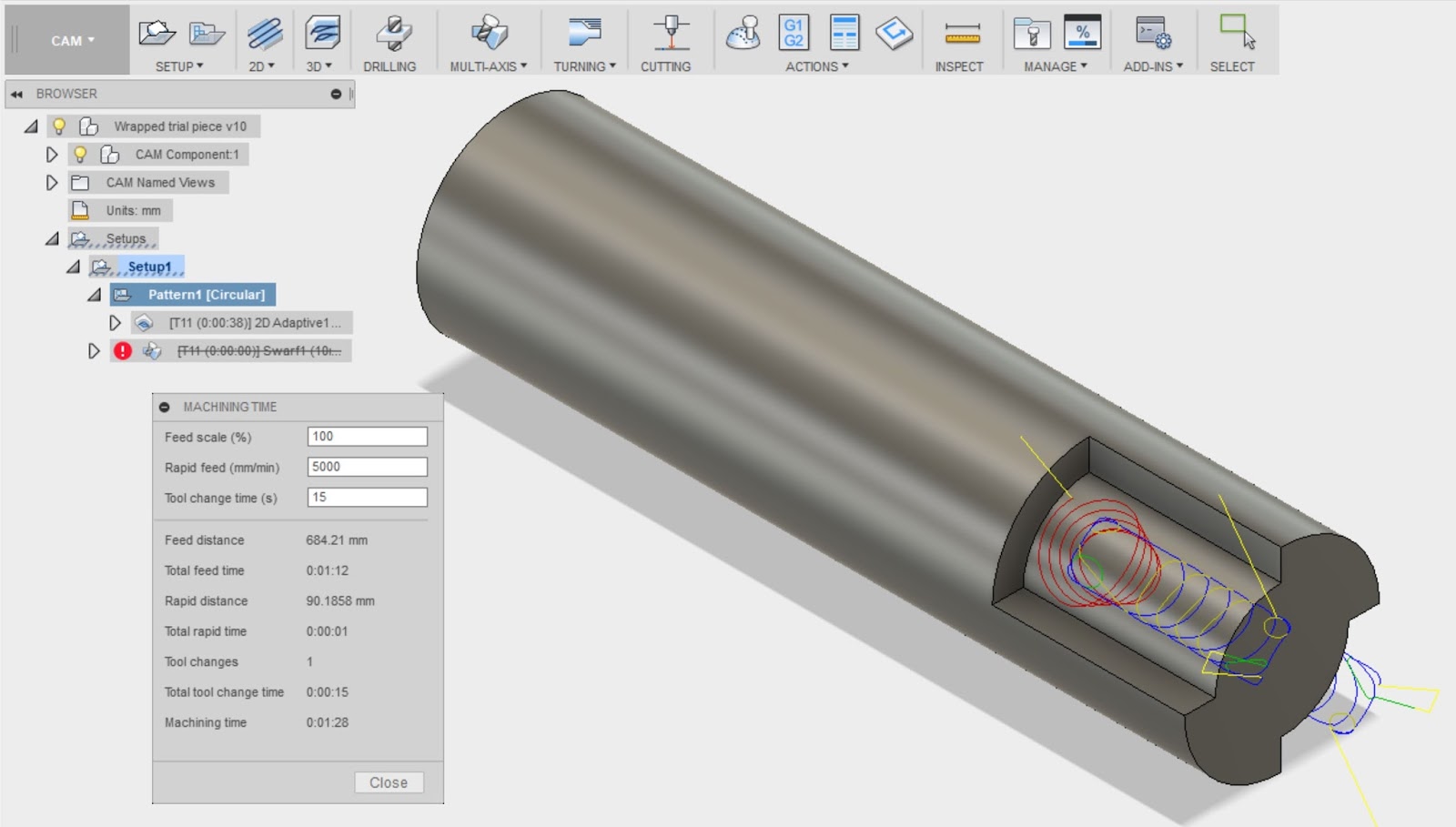
From the post processor:
The actual feedrates coming out of the post processor are in the aforementioned range of 100 - 300. Given the estimated total machine time of 1:28, it's clearly happening a lot slower than the post processor imagined it would. Perhaps if I could be arsed, I'd time the whole cycle to get an idea of the magnitude of the difference....
- The calculated feedrates in the g code seem to be too low by an order of magnitude at a guess.
- The scaling factors for the feed rates (G00 and G01) in the controller seem to be significantly different - by a factor of around 3-4.
By running code from MDI, it's possible to do a side-by-side comparison of the G00 and G01 feed rates. The feedrate for G00 is 1400 (set in parameters) and a similar G01 requires 5000:

So - what can be done in the post processor? And what if anything can be done with the controller?


No comments:
Post a Comment