So far I've made the main drive housings / brackets for the X and Y axis, as well as the cover plate for the Y axis. That was a great learning exercise and my first proper CNC machining.
I previously modelled up the cover for the Y axis in CAD but go distracted before getting round to doing the CAM for it, let alone actually machining the damned thing.
Here's the X axis body, waiting for its cover:
And this is where it goes, on the LH end of the table. The micrometer dial comes off and in its place goes a toothed belt and the housing for the belt and motor:
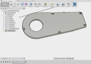
Here's the CAD model for the cover. It was drawn up in the same CAD space as the housing itself so that it is linked to the design paramters. There's actually a fair bit else in there such as the soft jaws and the stock model that was used for the machining of the main housing. I can just turn off visibility of those and focus on the housing and cover.
Given that this is very similar to the cover for the Y axis, it makes sense to use CAM "templates". These allow you to save a toolpath or group of toolpaths that you've spent ages devising for reuse later. That way you don't have to completely repeat the whole exercise.
So I went into the Y axis cover CAM and saved those operations as a template. Brought them in to the X axis CAM environment and rejigged them for those operations. Obviously you have to point the toolpaths at the required geometries, as those were lost when you saved the template, but it's considerably quicker than starting from scratch again and I recall a fair bit of buggerage getting the toolpaths working correctly the first time round. Here's how you do it - select the operations, right click and "Store As Template":
And in the case of the 2D Profile toolpath (used to "cut out" the external cover profile from the stock), the "tab" positions had to be redefined. Ideally the exact same positions should be used for the roughing and finishing Profile operations to avoid ploughing your tool into an existing tab during the finish pass. Best thing here is to define points in the CAD sketches which can be picked up as tab positions.
Similarly, the stock orientation needs to be defined in the setup, so a centre line drawn in the cover sketch is helpful - you can pick it up and define that as your X axis for the CAM operation. Then the stock will be aligned in a sensible orientation. This sketch includes the tab positions and the centre line, as well as the basic outlines for the body, cavity and fixings. The purple lines indicate that they are projected from the actual body:
The stock dimensions need to be defined too, so here they are based on actual measurements (extrusions are rarely bang on nominal!), as well as the allowance for the fixings at the LH end of the stock. As you can see, the triad (work coordinate system) for the cover CAM (in the middle of the large hole) is different to the origin and triad for the CAD model (at the top right of the window). That's because I want to mount it this way in the machine. No reason - I just felt like that.
Here are the final toolpaths once the template operations have been rejigged. I've also ditched the M3 clearance hole operations, as these fixings are all M4:
Here's the simulation, showing the final body that results. The tabs are visible and the chamfers etc look correct. Note that the heavy-ish roughing out of the large hole is done before the external profiling. Once the body is only supported by the tabs, the remaining operation is just the chamfering which doesn't put much load on them.
I'm certain to bugger about a bit more with this before actually making any swarf but it looks and feels 98% right.
Now to set up the machine, tools and stock....
Retrofitting 1983 Shizuoka AN-SB CNC milling machine, Bridgeport mill, Colchester Bantam lathe and 1982 Tree UP-1000 CNC lathe with modern controls - and other workshop stuff
Subscribe to:
Post Comments (Atom)
LinuxCNC hell - can Gemini AI help?
Oh no, not AI again? Oh yes. Although ChatGPT got a whole load of exposure and caused a whole load of excitement last year, AI is a bit more...

-
Setting up the servo tuning(?) software: Having spent a couple of hours yesterday pratting about with the PID controllers for the X and Z ax...
-
Right, so having gone through the motions with the X axis (cross slide), I should now be able to set up the Z axis (longitudinal) encoder an...
-
The bearing arrived as expected this morning. Took a few minutes to make up a 42 x 25.5 x 7mm thrust washer, then fitted the bearing and was...


No comments:
Post a Comment