The stock is ready and waiting in the workshop. I bought enough material for all of the X and Y (and Z) axis components. However, I need to mount it on the machine. Previously when doing the Y axis cover, I bolted the stock to a carrier. I'll do the same here.
The cover stock is imperial sized - 3/8" x 4" 6082T6 extrusion and I have some thicker section 4" scetion that I can bolt it to.
I want to use countersink bolts to reduce the risk of collision(!), so it's best to get the holes in the cover and support deadly aligned. The best approach is to clamp them together, then drill and tap them together as one body:
- Drill to full depth (28mm) with tapping drill (using 5.25mm for an M6 thread).
- Drill through the cover stock with M6 clearance drill (actually 6.0mm as I want and need minimal clearance as such).
- Machine tap to 20mm or so (to get the tap perfectly concentric).
- Countersink the hole to full head depth.
- Finish machine tapping to full depth using cordless driver (with torque limit!).


Done:

And slap it in the nice new machine vise:
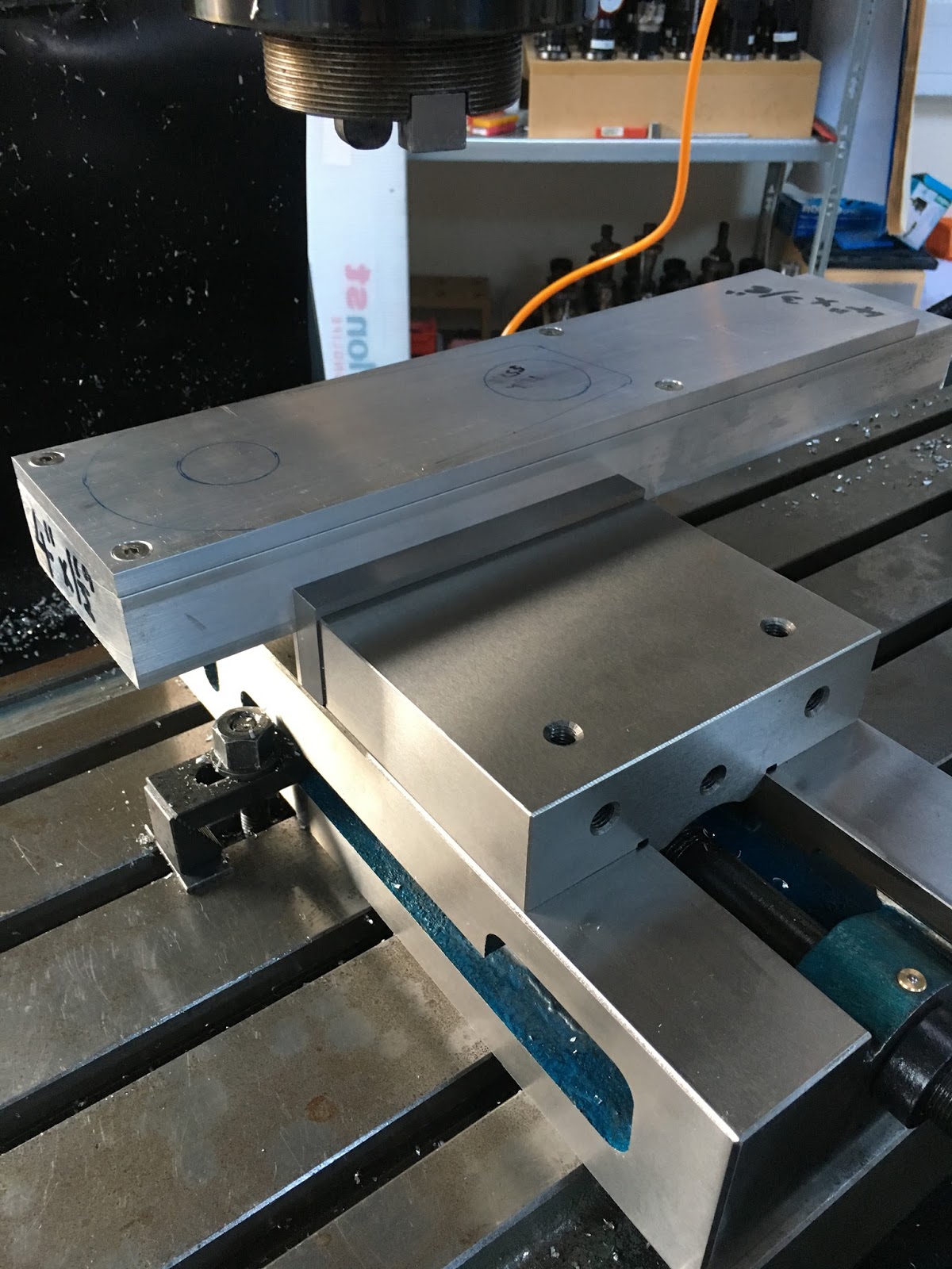
Tool setup:
With a turret mill, there is limited quill movement (150mm here), so you have to be careful how you position the work relative to the head. The total quill movement has to accommodate the different tool lengths as well as the Z moves required for the machining. That means also that the table height has to be positioned carefully, within a limited range. So if your range of <total tool length and movement> for the tools you plan to use amounts to 120mm (for instance), you have only a 30mm range of table heights. If you get it wrong, you will only find out when you try to run the program in the machine and the controller tells you there is an out of limit value in Z at some line or other.
I devised a simple(?) spreadsheet for this purpose. Requires you to type in the range of Z for each tool (bottom height to clearance height, IIRC), along with its tool offset. This then tells you the range of Z values that is acceptable for the position of the stock origin as defined in the setup used. A bit of cranking on the table and Bob's your auntie.
This is the tool setup sheet:


This is the tool length offset spreadsheet for this part - after triple checking all the (50) tools:

All done. G54 zero is set on the top surface of the stock in the middle of the large hole. Swarf time approaches!
UPDATE - 10th feb:
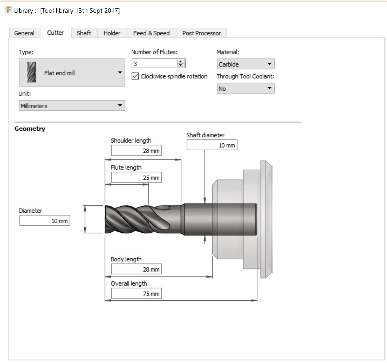
I remember now that I bought some standard length 10mm, 55 degree end mills from APT. As I'm not roughing out any deep cavities, it makes sense to use this std length part - more rigid / less chatter etc.
Updated the tool library - duplicated tool 11 to create a shorter version. The std cutter is 75mm overall, the long series is 100mm overall. This is how it's done - pretty simple:

And the tool length spreadsheet is updated:

I need to touch off the new tool to get the tool length offsets spot on in the controller before I finally get machining but for now I've just subtracted 25mm from what I had. That's good enough fot the spreadsheet and for the Fusion CAM.
I devised a simple(?) spreadsheet for this purpose. Requires you to type in the range of Z for each tool (bottom height to clearance height, IIRC), along with its tool offset. This then tells you the range of Z values that is acceptable for the position of the stock origin as defined in the setup used. A bit of cranking on the table and Bob's your auntie.
This is the tool setup sheet:


This is the tool length offset spreadsheet for this part - after triple checking all the (50) tools:

All done. G54 zero is set on the top surface of the stock in the middle of the large hole. Swarf time approaches!
UPDATE - 10th feb:
I remember now that I bought some standard length 10mm, 55 degree end mills from APT. As I'm not roughing out any deep cavities, it makes sense to use this std length part - more rigid / less chatter etc.
Updated the tool library - duplicated tool 11 to create a shorter version. The std cutter is 75mm overall, the long series is 100mm overall. This is how it's done - pretty simple:
And the tool length spreadsheet is updated:

I need to touch off the new tool to get the tool length offsets spot on in the controller before I finally get machining but for now I've just subtracted 25mm from what I had. That's good enough fot the spreadsheet and for the Fusion CAM.


No comments:
Post a Comment