When I fitted the Y axis ballscrew, I failed to check the movement range. If I had, I would have noticed that the saddle wasn't able to move right to the back of the knee. Clearly something is binding and given that the ballnut is the only changed component, I suspect it's fair to assume that the ballnut flange is hitting something.
In fact, you can see into the inside of the knee assembly by sliding back the cover. The problem is pretty clear - as expected, the flange of the new ballnut is clashing with the Z axis crank shaft, where the bevel gear bearing is housed:
Whipping the bearing housing off the front of the knee reveals the ballnut mounting screws. The (larger) flange is visible.
It's quick and easy to withdraw once the 2 screws have been removed. It was nicely oiled, so the lube pump seems to be doing its job.
The yoke (ballnut housing) has a relieved surface at about 8 o'clock. It's obviously there to provide clearance to the bevel gear bearing housing.
I'm going to be removing the corner of the ballnut using an angle grinder. The last thing I want is grit getting into the ballnut, so I wrapped the ballscrew / ballnut assembly in clingfilm.
A piece of steel tube to protect the exposed ballscrew, in case I have a wobble or a slip.
And a little booth to contain the grit and sparks, to prevent them from getting everywhere.
Like a lot of my work, it's not pretty but will do the job:
Reterminating the motor phase connections:
It took a few sessions with the angle grinder to get the flange ground back. There's a lot of heat generated, so in between being nasty to it, I let the ballnut cool down and turned to the motor. As mentioned before, I wanted to get rid of the Mate And Lock style connector in the motor wiring by soldering the cable directly to the stator. Like this. The yellow wire is the ground connection to the motor housing.
Job done. Haven't tested it yet but 95% confident it should still work.
Reassemble DRO scale in new position:
Drilled and tapped the new M6 holes, shortened the cover and refitted the scale. Looks good to me. Apart from the "machining" of course.
M12 nut for handwheel:
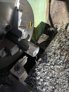
Still haven't got round to making a nut for the Y axis handwheel. The ballscrew was machined to my drawing, including an M12 (fine) thread for the locknut. That's a non-std pitch (1.5mm), so I need to make up a nut for it. I have the required tap and some handy hex bar.
Drill and chamfer front, then partially part off:
Thread and back chamfer before parting off finally:
There:


No comments:
Post a Comment