
The VFD and filter are the same ones used on The Shiz - 2.2 / 3kW 230V single phase input. The filter is by Schaffner and is a custom part for this VFD. You mount the VFD on top of the filter box and the brown and blue wires are just the right size to connect up to the VFD terminals. Very neat!
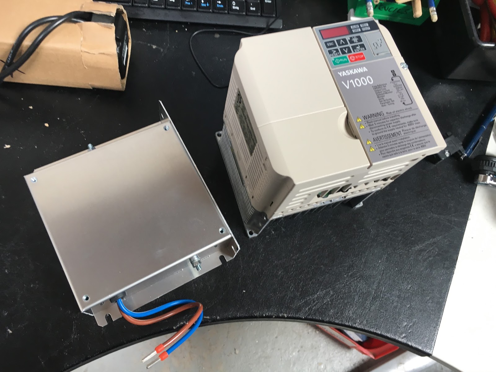
Here it is, connected up:

At this point, curiosity got the better of me. The various cover simply clip together and conversely they can be unclipped easily. So let's have a look inside:

Nippon Chemicon caps, a simple flyback power supply, some relays and a load of NTCs(?) - 6 of them - presumably the inrush limiting devices. The alternative would be a soft start resistor and relay (or triac).

This is the switching FET for the PSU, I'm guessing:

Nothing too radical. The lower board (half hidden) connects up the IGBT bridge, braking device and rectumfrier bridge (possibly all in one module?). The board in the housing is presumably the microcontroller that does the clever stuff, unless there's another one hidden on the bottom board.

Mockup / build continues:
Here's what I'm thinking so far. The DIN rail terminal strip will actually mount on the door.

First, I hacked a bloody great hole in the front panel. I thought I'd try my air powered nibbler but the compressor is simply too small in terms of both CFM and tank size, so I soon gave up on that idea. Similarly the air hacksaw was a dead loss. No surprise there - I bought a Bambi (almost) silent compressor mainly for my power drawbar and gear selection actuators but was still surprised how incapable it is of operating any of the air tools.
Finally, I used my mains powered jigsaw to do the business. I got through 3 of the laughable Chinesium jigsaw blades that I got from ebay recently. I wasn't expecting much of them but the "cobalt HSS" blades surely should have managed to cut through a mild steel sheet without melting?!! You get what you pay for and true enough, I didn't pay much for these....
Used my clinch nut kit to insert some M4 rivnut things to hold the controller in place. Seems to have got that bit sorted.

And mounted the Siemens mains isolator on the front panel. Nice switch - properly IP65 and fits together well. There you go:

The 48V PSUs have front access mounting holes / slots but the 36V PSU only has threaded holes in its chassis. I need to be able to fit and remove the PSUs (and all of the other components) without having to remove the chassis plate to get to nuts etc from the back. I found a handy strip of loominum that will come in handy...

So I made up a simple plate for the 36V PSU. You need to be careful not to allow the screws to poke too far into the body of the PSU. One of the holes seemed to have an insulator and something fairly solid about 5mm in, so I carefully sanded a 6mm long screw to length.

Job done - can be mounted from the front now.

Then went mad with the drill, making pilot holes for the Rivnut-style inserts for the VFD, braking resistor, PSUs, servo drives etc. More pics later...


No comments:
Post a Comment